AutoCAD, codenamed "Maestro" with official release March 20, 2015. This is the 30th version of AutoCAD.
Previous AutoCAD version AutoCAD 2015 and next version AutoCAD 2017
New and/or enhanced functions | Still missing | Existing bugs | Tips & Tricks | Readme | Updates & Service Packs | Cascading Sequences | Links | New and Updated Command | Removed or Obsolete Commands | New and Updated System Variables
New and/or enhanced functions
New and/or enhanced functions
File format
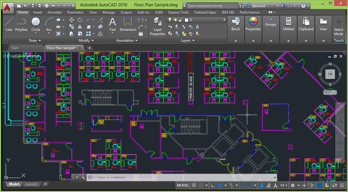
The DWG file format is the same as in AutoCAD 2013, 2014 and 2015: "AutoCAD 2013 Drawing". The DXF file format is also the same.
Revision Clouds
Three methods are now available on the Annotate Ribbon panel to create a revision cloud: rectangular, polygonal and freehand. REVCLOUDCREATEMODE system variable is used to remember the last method being used.
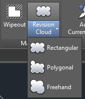
Grips on the revision clouds makes it possible to edit the size and shape easily. REVCLOUDGRIPS can be set to Off for legacy display of the grips.
Using the REVCLOUD command the new Modify options makes it possible to draw new revision cloud segments as well as erase selected portions of existing revision clouds.
DIM command
On the Annotate Ribbon tab the DIM (Dimension) command has been added. The dimension layer control is new and shows "Use Current" in the below image.
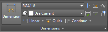
When DIM is used the dimensions are created on the layer specified. The new DIMLAYER system variable specifies a default layer for new dimensions.
The DIM command automatically creates the dimension type based on the object selected. The command prompt can be used to switch to another dimension type if needed.

When a dimension is created so it overlaps another similar dimension a menu gives the option to move, break up, replace the existing dimension or place the new dimension on top of the existing one.
A width sizing control makes it possible to specify a width for text wrapping when editing the dimension text.
Text
Mtext objects now have a Text frame property enabling you to create a border around the text.
The Match tool on the Text Editor ribbon is sticky making it possible to apply properties of the selected text multiple times within an Mtext object.
File Tabs
When AutoCAD starts the "Start" tab is showed. Before it was named "New Tab". The NEWTABMODE system variable has been renamed to STARTMODE and when set to 0 the Start tab is not displayed.
When creating a deployment there is a new option that enables you to show or hide the Start tab.
To get to the Start tab press Ctrl+Home or use the GOTOSTART command.
CLOSEALLOTHER is a new command that closes all drawings except the current one. This command is also available if you right click on a drawing tab and select "Close All Other Drawings".
Layouts
Now it's possible to drag and drop layouts to move or copy them to a location that is hidden if you have many layouts in a drawing. Drag to the right or left edge and the layout tabs will automatically scroll.
Right-click on a layout tab and there's "Dock above Status Bar" or "Dock Inline with Status Bar" available.
Status bar
The Status bar can automatically wrap onto two rows when needed.
Isolate Objects and Lock UI have been added to the Status bar customization menu.
The Lock UI tool now allows you to check and uncheck multiple UI elements without having to reopen the flyout every time.
Ribbon
GALLERYVIEW is a new system variable that enables control over the Ribbon galleries. 1 displays the thumbnail view and 0 displays the list view. Cell styles and Text Styles ribbon galleries will not display the list view.
Help
Single sign-on makes it possible to automatically sign into the Help documentation when you sign into the A360 account and vice-versa. Signing into the Help documentation enables you to Like a Help topic.
The UI Finder now includes the Status bar and application menu. UI Finder makes it easy to find location of UI elements from within the Help documentation. Click on the Find link and an animated arrow will point to the location of the tool in the Quick access toolbar, the Ribbon, Status bar or application menu.
Deployment/setup
How to change license type from Standalone to Network?
1. Open you system registry editor (Go to Start > Search > type regedit and hit Enter key)
2. Locate the key below and change Type value to 1
HKEY_LOCAL_MACHINE\SOFTWARE\Autodesk\AutoCAD\R20.1\ACAD-F001\AdLM
3. Create client license file, LICPATH.lic file, in Notepad.
e.g.
SERVER yourServerNemeHere 000000000000
USE_SERVER
Note: change yourServerNemeHere to your actual network license server name.
4. Place LICPATH.lic file in C:\Program Files\Autodesk\AutoCAD 2016\ folder
Note: Make sure that the LICPATH.lic file doesn't have hidden .txt extension.
5. Start AutoACAD 2016
API and more for Programmers
AutoCAD 2016 is a binary compatible release. Most custom programs that work for AutoCAD 2015 will also work in AutoCAD 2016.
Use either Visual Studio 2010, 2012 or 2013 for .NET development but 2010 will have limitations as .NET Framework 4.5 is not supported.
.NET applications should target Framework 4.5 but can in some cases work with an older version.
Major version number incremented to R20.1 from R20.0.
VBA
VBA 7.1 is the version of VBA.
Available as a separate download.
Obsolete AutoLISP functions:
getcfg - Retrieves application data from the AppData section of the acad20xx.cfg file.
setcfg - Writes application data to the AppData section of the acad20xx.cfg file.
Note: getcfg and setcfg are still available for compatibility, but might be removed in a future release. It is recommended to use the vl-registry-read and vl-registry-write functions as replacements.
Digitally signing of custom program files
Starting with AutoCAD 2016-based products on Windows, it is recommended to digitally sign your custom program files. By digitally signing a custom program file, you inform the user as to who published the custom program file and if any changes were made to the file after it was digitally signed. For information on digitally signing custom program files, see the "About Digitally Signing Custom Program Files" topic.
Each custom program file loaded is check for the existence of a digital signature. If a digital signature is found attached to a custom program file, the user is presented with information about the digital certificate and publisher that signed the file. The user can choose to continue to load the file, and optionally trust all files by the publisher of the file being loaded. If no or an invalid digital signature is found, the user is informed that the program file might not be safe to load and execute.
The ProgramData (per machine) or AppData (per users) folders, where Exchange store installers used to install Apps are no longer considered secure locations by AutoCAD 2016. In AutoCAD 2016, when the App gets loaded from these locations a warning message as displayed. You can avoid this warning message by digitally signing your modules. You can use SignTool.exe (for windows, located with Microsoft SDK toolkit) to digitally sign your C++ and .NET modules.
Example : signtool sign /f <PFX file name> /p <Password> FileToSign.dll
Similarly, you can use AcSignApply.exe (found in the AutoCAD installation folder) to sign the Lisp files. For more details on digitally signing please refer https://msdn.microsoft.com/en-us/library/ie/ms537361(v=vs.85).aspx
In AutoCAD 2016 Autodesk added the ability to digitally sign lisp files (.lsp, .fas and .vlx). They have the GUI version, AcSignApply.exe (which gets installed in the AutoCAD install folder) to sign the lisp files.
AcSignTool.exe is the commandline version of AcSignApply.exe. It is meant for signing lisp files in a batch process. AutoCAD doesn't need to be installed.
IMPORTANT: Please ensure that all files from this tool are copied in the same folder.
You can find the usage instructions by entering AcSigntool.exe /?
Additions and changes made to the ActiveX API in AutoCAD 2016 and AutoCAD 2016-based products.
Enums
AcSectionState2 (New)
acSectionState2Plane = 1
acSectionState2Slice = 2
acSectionState2Boundary = 4
acSectionState2Volume = 8
AcadSecurityParamsConstants (Obsolete)
ACADSECURITYPARAMS_ALGID_RC4 = 26625
AcadSecurityParamsType (Changed)
ACADSECURITYPARAMS_ENCRYPT_DATA = 1 (Obsolete)
ACADSECURITYPARAMS_ENCRYPT_PROPS = 2 (Obsolete)
Classes
IAcadDocument (Changed)
SaveAs - Method (Support for adding password protection has been removed)
IAcadPointCloudEx (Changed)
Segmentation - Property (New)
IAcadSection (Changed)
SectionPlaneOffset - Property (New)
SliceDepth - Property (New)
State2 - Property (New)
IAcadSecurityParams (Changed)
Action - Property (Constants ACADSECURITYPARAMS_ENCRYPT_DATA and ACADSECURITYPARAMS_ENCRYPT_PROPS are no longer supported)
Algorithm - Property (Obsolete)
KeyLength - Property (Obsolete)
Password - Property (Obsolete)
ProviderName - Property (Obsolete)
ProviderType - Property (Obsolete)
IAcadShadowDisplay - Interface is only supported by the MentalRay renderer
AutoCAD 2016 System requirements
http://www.autodesk.com/autocad-win-sys-reqs-2016-ENU
As always with system requirements these are minimal requirements forAutoCAD to run. For professional usage you surely want to have much better hardware.
FlexNet version 11.12.1.4 for Autodesk Network License Manager
Supported operating systems for the license manager are:
Windows Server 64-bit: Windows 2012 Server or Windows 2012 RS Server
Windows 7 32-bit and 64-bit SP1 or later
Windows 8 or 8.1, 32- or 64-bit
Citrix: Citrix XenServer 6.0, XenDesktop 7, XenApp 6.5, FP2
More details here as well as Linux System Requirements and Mac System Requirements.
AutoCAD 2016 System Requirements
| Description | Requirement |
| Operating system | •Microsoft® Windows® 8/8.1 •Microsoft Windows 8/8.1 Pro •Microsoft Windows 8/8.1 Enterprise •Microsoft Windows 7 Enterprise •Microsoft Windows 7 Ultimate •Microsoft Windows 7 Professional •Microsoft Windows 7 Home Premium |
| CPU Type | Minimum Intel® Pentium® 4 or AMD Athlon™ 64 processor |
| Memory | For 32-bit AutoCAD 2016: 2 GB (3 GB recommended) For 64-bit AutoCAD 2016: 4 GB (8 GB recommended) |
| Display resolution | 1024x768 (1600x1050 or higher recommended) with True Color |
| Display Card | Windows display adapter capable of 1024x768 with True Color capabilities. DirectX® 9 or DirectX 11 compliant card recommended but not required. |
| Disk Space | Installation 6.0 GB |
| Pointing Device | MS-Mouse compliant device |
| Media | Download and Installation from DVD |
| Browser | Windows Internet Explorer® 9.0 (or later) |
| .NET Framework | .NET Framework Version 4.5 |
| Additional requirements for large datasets, point clouds, and 3D modeling | Memory: 8 GB RAM or greater Disk Space: 6 GB free hard disk available, not including installation requirements Display Card: 1600x1050 or greater True Color video display adapter; 128 MB VRAM or greater; Pixel Shader 3.0 or greater; Direct3D®-capable workstation class graphics card. Note: 64-bit Operating Systems are recommended if you are working with Large Datasets, Point Clouds and 3D Modeling. |
Still missing
Still missing. Wish list for the next time.
Unfortunately there is no tooltip or preview image when holding the mouse over a layout tab name in the vertical layout list. This makes it hard to see layout names that are too long to show completely.
When moving objects the objects in the original position are displayed with a faded deletion effect. For consistency this should also apply to rotating and scaling of objects but it does not.
Existing bugs
Existing bugs, defects, feature limitation or other issues.
When resizing the AutoCAD application window the drawing area is not scaled correctly during the actual resizing.
When resizing the AutoCAD application window the Status bar automatic wrapping is not always working.
Sometimes if you sign a VLX file with a digital signature it will not load in AutoCAD. Typically this happens when DCL is involved but sometimes it happens even without any DCL involved.
"Auto Publish Settings" and "Block Editor Settings" dialog boxes are not centered like other dialog boxes in OPTIONS.
Certain slide images (.sld) can cause problems with text not being plotted. After viewing these slides with VSLIDE or through AutoLISP DCL true type font text is not seen in plot preview or being plotted. Here's a slide that causes this issue. AutoCADbug.sld
Enhanced Attribute Editor (EATTEDIT) is missing & in block names containing &. For example a block named a&b shows up as ab.
Tips & Tricks
Tips & Tricks
AutoCAD 2016 also is referred to as ACAD2016 or ACAD 2016.
AutoCAD 2016 product key is 001H1.
Default command line to start AutoCAD 2016: "C:\Program Files\Autodesk\AutoCAD 2016\acad.exe" /product ACAD /language "en-US"
How to to change the license from Standalone to Network:
The registry location to change the installation from Standalone to Network for AutoCAD 2016 is here:
HKEY_LOCAL_MACHINE\SOFTWARE\Autodesk\AutoCAD\R20.1\ACAD-F001:409\AdLM
ACAD-E001 is for vanilla AutoCAD.
Change the type for the installation using any of these values:
1 – Network
2 – Standalone
3 – Multiseat Standalone
In vanilla AutoCAD without service pack:
Command: _vernum
_VERNUM = "J.51.0.0 (UNICODE)" (read only)
Readme
Readme
Available online here.
This readme contains the latest information for Autodesk AutoCAD 2016 and Autodesk AutoCAD LT 2016. For reference, save or print this document.
It is strongly recommended that you read this entire document before you install this product.
Before Installation
- It is recommended that you first install all Windows® updates prior to installing the product.
DWG Convert, Etransmit, and Archive
- The ZIP option with the DWGCONVERT, ETRANSMIT, and ARCHIVE commands now creates UTF-8 ZIP files. This means that if you package drawings and other files that have names that include extended text font characters, the names will not display correctly if you use ZIP utilities that do not support UTF-8 format ZIP files. Use ZIP utilities such as 7-Zip to correctly display and extract these files.
Autodesk 360 Sync
- Before you reopen a file that you have saved and closed in Autodesk 360, allow additional time for the automatic sync feature to set the new path for linked files such as xrefs. If the repathing process is not complete, the drawing file will be locked when you open it, and you might get an error.
Design Feed
- The Design Feed palette might not update immediately after you save a drawing in Autodesk 360. To accelerate the save operation, right-click the Autodesk 360 icon on the Windows taskbar, and select Sync Now.
OSMODE
- A setting of 1024 will turn on the GCEN osnap, the geometric centroid. Script files and Lisp routines, that previously used 1024 to clear all osnaps, now need to use 0 instead. Bit-codes that include 1024 will enable the GCEN osnap.
Feature-Specific Requirements
- Referencing Point Clouds and Coordination Models in AutoCAD is supported only on 64-bit operating systems.
- Point Clouds and Coordination Models cannot be displayed in a 2D wireframe visual style or when hardware acceleration is turned off.
- Point Clouds cannot be viewed in a Windows remote desktop session. See the Autodesk ReCapTM Readme for more information.
- Rendering and Model Documentation are computation-intensive features, and it is highly recommended that you work with these on 64-bit operating systems.
Product Help
- Product Help is available online and is not installed with the product by default. If you do not have continuous internet access and want to install Help locally with the product, you can start the Help installation at the end of the product installation. Alternatively, you can download offline Help from the product Help menu any time that you have an internet connection.
Updates & Service Packs
Updates & Service Packs & Hotfixes
Autodesk® AutoCAD® 2016 Internet Security Hotfix
Autodesk® AutoCAD® 2016.0.10 Update HP Driver Hotfix
AutoCAD 2016.0.10 Update is only available to download from the Autodesk Account or via Autodesk desktop app.
See our blog post AutoCAD 2016 Hotfixes
Cascading Sequences
Cascading Sequences for Autodesk 2016 Products
Understanding Cascade Licensing for Autodesk Products
Links
Links.
Autodesk's AutoCAD 2016 Discussion Group:
http://forums.autodesk.com/t5/AutoCAD-2013-2014-2015/bd-p/706
AutoCAD 2016 Help online: http://help.autodesk.com/view/ACD/2016/ENU/
VBA Microsoft Visual Basic for Applications Module can be downloaded here.
AutoCAD subscription members can download AutoCAD 2016 from the Autodesk Account page.
Download a free trial of AutoCAD 2016: http://www.autodesk.com/products/autodesk-autocad/free-trial
Find the certified and recommended computer hardware for the products or suites you are planning to install. For more information, go to www.autodesk.com/hardware.
To download and install the latest hardware certification XML file, visit http://www.autodesk.com/autocad-graphicscard.
For developers: http://www.autodesk.com/developautocad
If you want to participate in the Beta testing for the next release of AutoCAD (AutoCAD 2017) visit http://beta.autodesk.com.
JTB World Blog posts about AutoCAD 2016.
All Autodesk beta programs are run from http://beta.autodesk.com.
New and Updated Command
New and Updated Commands:
The following commands are new and updated in AutoCAD 2016.
| New commands | Description |
| CLOSEALLOTHER | Closes all other open drawings, except the current active drawing. |
| CMATTACH COORDINATIONMODELATTACH |
Inserts references to coordination models such as NWD and NWC Navisworks files. |
| DIGITALSIGN | Provides a separate command to add a digital signature to a drawing. Removes the Digital Signature tab from the SECURITYOPTIONS command. |
| GOTOSTART | Switches from the current active drawing to the Start tab. |
| PCEXTRACTCENTERLINE | Draws a centerline for a cylindrical segment of a point cloud. |
| PCEXTRACTCORNER | Marks the point of the intersection between three detected planes in a point cloud. |
| PCEXTRACTEDGE | Infers the edge between two planes and draws a line to mark the edge. |
| PCEXTRACTSECTION | Generates 2D geometry from a point cloud that contains section objects. |
| POINTCLOUDCROPSTATE | Controls saving, restoring, and deleting point cloud crop states. |
| RENDERENVIRONMENTCLOSE | Closes the Render Environment & Exposure palette. |
| RENDEREXPOSURECLOSE | Closes the Render Environment & Exposure palette. |
| RENDERWINDOW | Displays the Render window. Replaces the RENDERWIN command. |
| RENDERWINDOWCLOSE | Closes the Render window. |
| SCRIPTCALL | Executes a sequence of commands the same as the SCRIPT command, with the additional capability of also executing nested scripts. |
| SECTIONSPINNERS | Sets the default increment value for the Section Offset and Slice Thickness controls in the Section Plane Contextual Ribbon tab. |
| SYSVARMONITOR | Displays the System Variable Monitor dialog box. |
| Updated commands | Description |
| 3DORBIT | Rotates the view in 3D space, but constrained to horizontal and vertical orbit only. |
| 3DOSMODE | Sets running 3D object snaps. |
| ANIPATH | Saves an animation of a camera moving or panning in a 3D model. |
| BACKGROUND | Defines the type, color, effects and position of the background for a named view. |
| DIM | Creates multiple types of dimensions within a single command session. |
| DISTANTLIGHT | Creates a distant light. |
| FREESPOT | Creates a free spotlight which is a spotlight without a specified target. |
| FREEWEB | Creates a free web light which is a web light without a specified target. |
| OPTIONS, Online tab | Automatic saving to your A360 Drive has been removed. Instead, save or copy the drawing files that you want to upload to your A360 account directly to your local A360 Drive folder. |
| PAGESETUP | Controls the page layout, plotting device, paper size, and other settings for each new layout. |
| PLOT | Plots a drawing to a plotter, printer, or file. |
| POINTLIGHT | Creates a point light that radiates light in all directions from its location. |
| RENDER (-RENDER) |
Creates a photorealistic or realistically shaded image of a 3D solid or surface model. |
| RENDERENVIRONMENT | Displays the Render Environment & Exposure palette. Controls image-based lighting and photographic exposure for a rendered image. |
| RENDEREXPOSURE | Displays the Render Environment & Exposure palette. Controls image-based lighting and photographic exposure for a rendered image. |
| RENDERPRESETS (-RENDERPRESETS) |
Displays the Render Presets Manager palette and manages the render presets of a drawing. |
| RENDERWIN | Displays the Render window without starting a rendering operation. |
| REVCLOUD | Creates a revision cloud. New options for modifying an existing revision cloud and creating rectangular and polygonal revision cloud have been added. Rectangular is the new default revision cloud creation method. |
| RPREF | Displays the Render Presets Manager palette and manages the render presets of a drawing. |
| SECTIONPLANE | Creates a section object that acts as a cutting plane through 3D objects and point clouds. A new type of section object, slice, has been added. |
| SECURITYOPTIONS | Revises and adds security controls. Removes the Digital Signature tab, moving the controls to the new DIGITALSIGN command. |
| SPOTLIGHT | Creates a spotlight that emits a directional cone of light. |
| TARGETPOINT | Creates a target point light. |
| UCS | Sets the origin and orientation of the current user coordinate system (UCS). |
| WEBLIGHT | Creates a precise 3D representation of the light intensity distribution of a light source. |
| VIEW | Saves and restores named model space views, layout views, and preset views. |
| -VPORTS | Creates multiple viewports in model space or in a layout (paper space). |
Removed or Obsolete Commands
Removed or Obsolete Commands and System Variables:
In this release, the following Commands have been deprecated:
| Commands | Description |
| DIM1 | Accesses Dimensioning mode commands. Obsolete but still included in the product to maintain legacy script compatibility |
| NEWTAB | Displays a New Tab which provides access to files, learning resources, A360 and more. Replaced by the Start tab. Use STARTMODE to control the display of the Start tab. Use GOTOSTART or Ctrl+Home to switch focus from the current drawing to the Start tab. |
| RENDERWIN | Displays the Render window without starting a rendering operation. Replaced by RENDERWINDOW. |
| WELCOMESCREEN | Displays a New Tab and is now removed. |
In this release, the following System Variables have been deprecated:
| Commands | Description |
| ONLINEDOCMODE | Indicates whether copies of your drawings and linked files are uploaded automatically to Autodesk A360. Automatic saving to your A360 Drive has been removed. Instead, save or copy the drawing files that you want to upload to your A360 account directly to your local A360 Drive folder. |
New and Updated System Variables
New and Updated System Variables:
The following 28 system variables are new in AutoCAD 2016.
| New system variables | Description |
| CMFADECOLOR | Controls the amount of black blended on all attached coordination models. |
| CMFADEOPACITY | Controls the amount of dimming through transparency for all attached coordination models. |
| DIMLAYER | Specifies a default layer for new dimensions. |
| DIMPICKBOX | Sets the object selection target height, in pixels within the DIM command. |
| DIMTXTRULER | Controls the display of ruler when editing a dimension text. |
| EXPVALUE | Specifies the exposure value to apply during rendering. |
| EXPWHITEBALANCE | Specifies the Kelvin color temperature (white balance) value to apply during rendering. |
| GALLERYVIEW | Controls the type of preview in the ribbon drop-down galleries. |
| IBLENVIRONMENT | Enables image-based lighting and specifies the current image map. |
| LEGACYCODESEARCH | Controls whether searching for executable files includes the current and drawing folders. |
| LINEFADING | Controls whether line displays are faded when hardware acceleration is on and you have exceeded the line density limits. |
| LINEFADINGLEVEL | When hardware acceleration is on, controls the intensity of the line fading effect. |
| POINTCLOUD2DVSDISPLAY | Turns off or on the bounding box and text message when viewing a point cloud in the 2D Wireframe visual style. |
| POINTCLOUDEDGEDISPLAY | Specifies the type of edge preview displayed in a point cloud. |
| RENDERENVSTATE | Indicates whether the Render Environment & Exposure palette is open or closed. |
| RENDERLEVEL | Specifies the number of iterations, or levels, the render engine performs to create the rendered image. |
| RENDERLIGHTCALC | Controls the rendering accuracy of lights and materials. |
| RENDERTARGET | Controls the duration to use for rendering. |
| RENDERTIME | Specifies the number of minutes that the render engine uses to iteratively refine a rendered image. |
| REVCLOUDCREATEMODE | Specifies the default input for creating revision clouds. |
| REVCLOUDGRIPS | Controls the number of grips displayed on a revision cloud. |
| SECTIONOFFSETINC | Sets the default increment value for the section object slice thickness control. |
| SECTIONTHICKNESSINC | Sets the default increment value for section object offset control. |
| SELECTIONEFFECTCOLOR | Sets the color of the glowing highlighting effect on object selection. |
| STARTINFOLDER | Stores the drive and folder path from where the product was started. |
| STATUSBARAUTOWRAP | Controls line-wrapping in AutoCAD status bar |
| SYSMON | Specifies whether changes to system variables values are monitored. |
| WORKINGFOLDER | Stores the drive and folder path of the operating system's working folder or current directory for the process, which can be of interest to developers. |
| XREFOVERRIDE | Controls the display of object properties on referenced layers. |
And updated system variables.
| Updated system variables | Description |
| 3DOSMODE | Sets running 3D object snaps. |
| RENDERPREFSSTATE | Indicates whether the Render Presets Manager palette is open or closed. |
| SMOOTHMESHMAXFACE | Sets the maximum number of faces permitted for mesh objects. |