
My experience of AutoCAD 2012 (aka Ironman).
AutoCAD 2012 ('twenty twelve') was released on Tuesday, 22 March 2011.
This is the 26th version of AutoCAD.
Previous AutoCAD version AutoCAD 2011 and newer version AutoCAD 2013.
New and/or enhanced functions
New and/or enhanced functions and some bug fixes.
No New file format "AutoCAD 2010 Drawing" is used. The version number is 18.2.
The big news in AutoCAD 2012 are:
- Associate Array
- Autodesk Exchange
- Content Explorer
- Auto-Complete Command Entry
- Model Documentation + Import several new CAD formats
- Inventor Fusion
- In Canvas Viewport Controls
- Editable UCS Icon
- Performance Enhancements
- New AutoLISP Functions

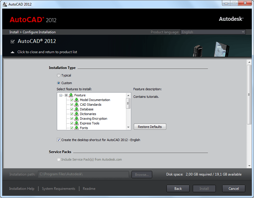
AutoCAD 2012 installation
The installer UI has been updated.
Create Deployment, Install Tools & Utilities or Install on this computer. See the System Requirements.

Installation Overview
The process of installing or deploying AutoCAD 2012 consists of the three main steps shown in the diagram above.
- Preparation is very important for achieving a trouble-free and successful installation.
- Entering Information varies depending upon the kind of installation or deployment you need.
- Installation or Deployment executes quickly once you have made and specified your choices.
You will either perform an installation on a single computer or create a deployment for multiple computers. In both cases, you decide whether to accept the typical default options or select your own options to configure a custom installation. Although the AutoCAD Installer has been designed to be self-explanatory, you can find answers to your installation questions in the FAQ provided here. Note that complete details for creating deployments are provided in the Network Administrator's Guide.
What kind of installation will you perform?
Here are the four main installation types with a summary of the data and decisions they require:
- Typical installation with default options. For a typical installation, begin with a proper preparation. Then, just click through the installer, providing your serial number, product key, and license information. Pre-selected components will be installed with AutoCAD.
- Custom installation with selected options. For a custom installation, in addition to the items listed above for a typical installation, you will also need to determine:
- Which of the additional bundled products (such as Autodesk Design Review) to install with AutoCAD.
- Which features (such as Express Tools) to install with AutoCAD.
- Select standard content libraries to install.
- Whether to accept the default to create a desktop shortcut.
- Whether to install any available service packs, either from Autodesk or from a local or network drive.
-
Typical deployment with default options. To create a typical deployment using default options, in addition to providing your serial number, product key, and license information, you will:
- Name your deployment.
- Specify a location for your administrative image.
- Specify whether you want a network log file.
- Determine whether to run installations to workstations in silent mode.
- Determine whether you want to create a client log file in the Temp directory of each workstation.
- Custom deployment with selected options. For a custom deployment, in addition to the items listed above for a typical deployment, you will also specify:
- Which of the additional bundled products (such as Autodesk Design Review) to install with AutoCAD.
- Which features (such as Express Tools) to install with AutoCAD.
- Whether to install any available service packs and whether to merge them with the deployment or append them.
- Whether to add additional files to the deployment.
- A folder or folders where support content will be installed.
- What modifications to make to the default search paths and the location of some program files.
- User preferences.
- Whether to enable access to communication channels, live updates, and RSS feeds.
- Whether to enable access to online resources.
VBA
VBA (Visual Basic for Applications) is still available as a separate installer.
http://www.autodesk.com/vba-download
UPDATE: As of January 31, 2014, Autodesk is no longer authorized to distribute VBA 6 or earlier versions of VBA for use with Autodesk AutoCAD and other Autodesk products. This change affects the availability to download and install VBA for Autodesk AutoCAD 2013 or earlier.
Migration
Simplified Migration to AutoCAD 2012: New and enhanced tools make it easier to migrate your custom settings or reset AutoCAD to the default install settings. Improved handling of tool palettes and new migration of custom materials help ease the transition to AutoCAD 2012, and a new reset tool helps easily return to default settings.
Autodesk Vault
Autodesk Vault is available for AutoCAD 2012 subscription customers.
- Faster startups, particularly running Vista or Windows 7.
- Switch ribbon tabs is nearly instantaneous.
- Opening large 3D models with lofts and meshes.
- Initializing orbit command and orbiting large 3D models.
- Improved performance with large, dense hatch objects.
- Selection highlighting, license checkout, running LISP routines.
In AutoCAD 2012 The ARRAY command has been largely improved and is now creating a new array object that is also associative by default. The old AutoCAD array dialog box is gone (ARRAYCLASSIC available in SP1) with only –ARRAY as classic command line command and the ARRAY command is instead working with the command line, properties and the Ribbon.
ARRAYRECT, ARRAYPATH, ARRAYPOLAR, ARRAYCLOSE and ARRAYEDIT are new commands. ARRAYEDITSTATE and ARRAYTYPE are new system variables.
Associativity allows you to quickly propagate changes throughout an array by maintaining relationships between items. Arrays can be associative or non-associative.
- Associative. Items are contained in a single array object, similar to a block. Edit the array object properties, such as the spacing or number of items. Override item properties or replace an item’s source objects. Edit an item’s source objects to change all items that reference those source objects.
- Non-associative. Items in the array are created as independent objects. Changes to one item do not affect the other items.
To edit the array properties, use ARRAYEDIT, the Properties palette, Ribbon or grips.


Apply Item Overrides: Ctrl+click items in the array to erase, move, rotate, or scale the selected items without affecting the rest of the array. Reset the array to remove all item overrides.
Replace items: Replace selected items with other objects. Any item overrides are maintained. You can also replace all items that reference the original source objects, rather than selecting individual items.
Edit Source: To edit an item’s source objects, activate an editing state for a selected item. All changes (including the creation of new objects) are instantly applied to all items referencing the same set of source objects. Save or discard your changes to exit the editing state.
There are unfortunately a few bugs still in the new Array command that hopefully soon will be squished either as a hotfix or in AutoCAD 2012 Update 1 (AutoCAD 2012 SP1).
There is no LISP API to create and edit the new array object.
What if a drawing with the new Array object is opened in AutoCAD 2011 or older versions? The Associative block is a static anonymous block and all arrayed objects are also anonymous blocks. So you would need to explode twice to get the individual objects back.
Copy Tool
The Copy tool includes a new Array option that enables you to create a linear, non-associative array. You can enter the distance between a specified number of copies or enter the number of copies to fit between two specified points.

AutoCAD 2012 introduces AutoCAD Content Explorer. It overlaps to some extent with the old Design Center and comes via Autodesk Labs Project Snap.

Content Explorer is available on the Plug-ins ribbon tab and comes with the commands CONTENTEXPLORER and CONTENTEXPLORERCLOSE and system variable CONTENTEXPLORERSTATE.
Content Explorer aggregates design content from different folders that have been specified for monitoring by the Content Service (that is using Lucene for index/searching).
With Content Explorer you can index design content for quick access, catalog the objects in each file, and search for content in local folders (not external drives), network folders (not Windows network drives), and the Autodesk Seek Library.
With Content Explorer, you can
- Browse and search design content in local folders, network folders, and the Autodesk Seek Library and immediately access files and objects from within the AutoCAD environment
- Browse into DWG files and access and insert blocks, layers, linetypes, styles, etc.
- Search for objects, all text, attributes (including block attributes), and files in specified local and network folders.
- Pinpoint specific block references or text strings and automatically navigate to the containing file
- Open any file from Content Explorer and zoom to any attribute within it
- Save search parameters for instant access to design content that meets your design needs
- Customize how search results are displayed to streamline your work environment
- Right-click and select Open and Find text to open the drawing and locate any text within.

All text and attributes in the files are indexed, including block attributes. In addition, the following objects are indexed when a folder is selected for monitoring:
- Block definitions
- Block references
- Dimstyles
- Layers
- Layouts
- Linetypes
- Multileaderstyles
- Tablestyles
- Textstyles
- Xrefs
- Hyperlinks
Manage Saved Searches in Content Explorer
The saved searches feature allows you to capture a certain search string in a single click.
You can eliminate all of the steps required to search for specific files or objects by saving the search string.
For example, you can save a search that locates all of the furniture created by a specific designer. Any time you want to quickly access furniture, select the saved search. Since the index is continuously updated, any new files that meet the search criteria are displayed every time the search is recalled.
You can also delete saved searches, edit the names of existing saved searches, and save new searches on the Saved Searches drop-down menu.
Advanced Searching with Content Explorer
Advanced searches can be performed using property:value pairings or boolean operators.
You can refine your searches by using string combinations and value pairings.
Use Property Name and Value Pairs
A property:value pair is the property name and specific value for which you want to search. To search for a property with a specific value, enter the data as property:value in the Search field.
For example, enter author:jsmith in the Search field to find all of the DWG files where the author was JSmith.
More than one property:value pair can be used in a search string. For example, you can search for all of the drawing files identified as seating which were created by jsmith by entering objecttype:seating author:jsmith in the Search field.
You can create custom properties and values for your files on the AutoCAD properties dialog box.
Use Attributes and Value Pairs
An attribute:value pair is the block attribute and specific value for which you want to search. To search for a block attribute with a specific value, enter the data as attribute:value in the Search field.
For example, enter Designedby:JohnDoe in the Search field to find all of the objects designed by John Doe.
Search Text for a Specific Value
With the basic search capability, you can enter a text string and the search engine will return all files with a file name, keyword, title, author, or other properties that meet the string criteria, as well as any files containing the string, and objects with names that match the text string. Sometimes this type of string search will return more results than you need.
Use the text:string pair to search only for text entities, such as leaders, fields, hyperlinks, MText, tables, or any other text that may show up on a drawing. This type of search parameter will not search file-level properties, such as Author or Title.
To search for a specific text string, enter the data as text:string in the Search field.
For example, enter text:reviewed in the Search field to find all of the files with text entities containing the string “reviewed.”
Search with wild cards
You can use wild cards when specifying search criteria.
* - Represents any number of characters within a string.
? - Represents a single character within a string.
The search engine assumes a trailing asterisk (*), so you do not need to put an asterisk at the end of a search phrase.
Search with Boolean Operators
You can use operators to further refine your search results.
For example, to search for all of the files identified as seating that were not authored by JSmith, enter objecttype:seating NOT author:jsmith in the Search field.
AND - Searches for x AND y in any order. The search granny AND smith returns anything containing both words.
OR - Searches for either x OR y. The search granny OR smith returns anything containing either word.
NOT - Searches for x but NOT y. The search granny NOT smith returns anything containing granny but not smith.
" " - Searches for the exact phrase contained within the quotation marks. The search "granny smith" returns everything containing the exact phrase granny smith.
Filter Results in Content Explorer
The filter lets you choose object types, specific dates, date ranges, and relative dates to display in search or browse results.
Filter settings persist throughout searches and browsing until they are changed or the filter is deactivated. If you do not get the search or browse results you expect, try checking your filter settings to make sure they are current.
Indexing Stages
The indexing occurs in three stages, with deeper indexing occurring with each stage. The stages can be determined by the thumbnails displayed in the Content Explorer window.

And after a while when indexing is ready...

| Stage | Icon Displayed | Description |
| 1 |  |
File has been discovered by the indexer. By the end of this stage, file name and standard Windows properties have been extracted. You can search for file names and Windows properties, but you cannot explore the content within the file. Note! Since all text and attributes in the files are indexed, the initial index of the files contained in the watched folders may take some time to complete. |
| 2 |  |
Thumbnail and DWG-specific file properties have been discovered. During this stage, all objects and any text in the drawing, including block attributes, are being indexed. You can now search for DWG properties, but you cannot explore the content within the file. |
| 3 |
|
File is completely indexed. You can now explore or search for content within the file. |
| ! |
|
There was an issue while indexing this file. Select the file and press CTRL+ I for more information regarding the issue. |


Tips
If the Sheet Set Manager dialog opens every time you open a file in Content Explorer, it is because of the SSMAUTOOPEN system variable setting. Change the setting to suppress the dialog.
If you plan to search folders on several different network computers, Content Service must be installed on each network computer and the folders added to the watched folder list for indexing. Any machine running AutoCAD or an AutoCAD vertical with Content Explorer can access the network machines running Content Service for real-time search results.
Autodesk Exchange provides a web-based experience directly within the product. Included are tabs that access the following sources of information:
- Home. Provides a wide variety of content, including announcements, expert tips, videos, and links to blogs. When enabled for online access, the Home tab also includes access to the Knowledge Base, Communication Center, and Subscription Center.
- Apps. Released 2011-06-13. See the blog post on Autodesk Exchange Apps
- Help. Opens the AutoCAD Help system.

The tabs for online sources are not available in all languages, products, and installations. Autodesk Exchange can be configured for offline use only, in which case only the Home and Help tabs are displayed.
The Autodesk Exchange is a modeless windows showed on top of AutoCAD but work in AutoCAD can be done. It can be minimized itself or together with AutoCAD when AutoCAD is minimized. Using Alt+Tab when Autodesk Exchange is minimized will not show the window even though it can be seen on the taskbar.
Options>System has Autodesk Exchange settings:
- Access online content (including Help) when available
- Offline Help browser:
- Internet Explorer (Supports all functionality)
- Default System Browser

It's not possible to get internal content or custom help files to integrate. The only option is to access it via the CAD Manager Feed button. Deployment Wizard or CAD Manager Control Utility can be used to enable the CAD Manager Channel.
To disable Exchange for all users at deployment, uncheck the option "Use Online Help from Autodesk when available" in the deployment wizard. The end-user can turn it back on in the Options dialog though.
In-canvas Viewport controls are displayed at the top-left corner of each viewport, and provide a convenient way of changing views, visual styles, and other settings.

The labels display the current viewport settings. For example, the labels might read
[+] [Top] [2D Wireframe]
You can click within each of the three bracketed areas to change the settings.
- Click + to display options for maximizing the viewport, changing the viewport configuration, or controlling the display of navigation tools.
- Click Top to choose between several standard and custom views.
- Click 2D Wireframe to choose one of several visual styles. Most of the other visual styles are used for 3D visualization.

VPCONTROL system variable controls whether the menus for viewport tools, views, and visual styles that are located in the upper-left corner of every viewport are displayed.

The UCS has been updated to allow direct manipulation. Select the UCS icon and use the multi-functional grips to change the UCS.

Easily move the origin, align the UCS with objects, and rotate it around the X, Y, or Z axis without having to access the UCS command.

When selected Properties give access to UCS icon On, UCS icon at origin, UCS per viewport and UCS Name.

Right click on the UCS Icon for more options. This is customizable using CUI.

Blend Tool
Create spline objects with options for tangent or smooth continuity between two curves with the new Blend tool. BLEND creates a spline in the gap between two selected lines or curves.
In below image the green spline is created by the blend command.

Valid objects include lines, arcs, elliptical arcs, helixes, open polylines, and open splines.
Layer Enhancements
A new layer management option enables you to quickly freeze specified layers in all viewports except the current one. You can access this functionality from the right-click menu in the Layer Properties Manager as well as from the Freeze option of the VPLAYER command.
![]()
Mtext Enhancements
The Mtext background mask has been updated to remember the last used fill color and border offset factor rather than always defaulting to red and 1.5.
MLeader Enhancements
To have more control over your leaders, you can now change the gap around Mleader text in a text frame. You can also extend the leader line to the text rather than ending at the text bounding box. Access the MLeader improvements in the Multileader Style dialog box.

When the Frame Text property is enabled, the Landing gap value specifies the distance between the text and the text frame.
Fillet, Chamfer, Blend, and Join
The Fillet and Chamfer tools have been updated to display a preview when passing the cursor over the second object in the fillet/chamfer selection. Now you can confirm and change the radius or distance values before even completing the command.
When using the Polyline option, the preview fillet arcs or chamfer lines are displayed for the entire polyline.
If the preview is not as desired, you can edit the fillet radius or chamfer distance/angle prior to completing the operation.
The Fillet tool now supports filleting of spline objects.
The new Blend tool creates spline objects with options for tangent or smooth continuity between two curves, speeding documentation time. It supports lines, arcs, 2D and 3D polylines, splines, helixes, and elliptical arcs.
The Join tool is streamlined to automatically combine selected objects using typical selection methods such as crossing or picking objects in any order. You are no longer required to select the source object first.
Spline Enhancements
Splines have been updated in AutoCAD 2012 to support periodic splines. When you specify the Close option for a spline, a periodic spline with C2 continuity between the start and endpoints is generated and the new Periodic property is listed in the Properties window.
An example of a periodic spline.

With Control Vertices shown.

Periodic behavior is also supported when rebuilding closed NURBS surfaces. When converting an analytical surface to a NURBS surface, a periodic NURBS surface is created if the end conditions of the surface allow for it.
AutoCAD 2012 provides more flexible and intuitive behavior with greater control when grip-editing fit points of splines. In addition, the knot parameterization property of the spline, which is displayed in the Properties palette when the method is set to Fit, has changed from a read-only text field to a drop-down list where you can specify chord, square root, or uniform knot parameterization. Changing the knot parameterization value is often useful when switching from editing the control vertices of the spline to editing the Fit points of the spline. It provides greater control over the shape of the spline as it passes through the Fit points.
The Kink option has been added to the Splinedit tool when selecting a Fit Points spline.
The Extend tool is enhanced to support splines when selecting objects to extend. The spline is extended while maintaining a curvature that is continuous with the original spline.
The 3D Edit Bar is enhanced to support splines and is accessible from the right-click menu when a spline is selected. It enables you to move the location of a point on the curve, change the magnitude of the tangency at the point, and change the tangent direction relative to the point.
Dimension Right-Click Menu
When you right-click with a dimension selected, you now have the option to Remove Style Overrides.

Tools
Save time by automatically generating intelligent documentation for AutoCAD, Inventor, and other models. Drawing views, edge display, and location are instantly updated when an engineering change is made.
Access the model documentation tools from the Drawing Views panel of the Annotate ribbon tab.
Using the Drawing View editing tools, you can easily modify drawing views after they’ve been created.
When changes are made to the source of a drawing view, various notifications appear.
Standards play a role in almost every aspect of documentation, including the representation of drawing views. You can specify drafting standards for new drawing views using the Drafting Standard dialog box, which is accessible from the dialog box launcher in the lower right corner of the Drawing Views ribbon panel. You can specify first angle and third angle projection methods, which support the ISO and ANSI standards.
The Export Layout tool has been updated to support new 2D View functionality in AutoCAD 2012. You can access this tool from the Save As>Save Layout as Drawing option in the Application menu.
Import a wide variety of other formats including SolidWorks®, Pro/ENGINEER®, CATIA®, Rhino, and NX®. Drawing views, edge display, and location are instantly updated when an engineering change is made.
The ability to import these file formats supports surfaces, solids, and 2D and 3D wire geometry. The data is translated to native AutoCAD geometry and inserted into the drawing as blocks. Parts and assemblies in the original models are preserved and replicated as nested blocks. After importing, you can freely modify the data using standard AutoCAD editing tools and document the 3D models using the new model documentation tools.

With access directly from the AutoCAD 2012 interface, AutoCAD WS web and mobile application for AutoCAD software allows you to stay connected to your designs over the web or from your mobile device.

Autodesk
Adds to the 3D conceptual design capabilities of AutoCAD and sets a new standard for professional 3D modeling ease of use. It enables you to flexibly edit and validate models from almost any source, helping you further experience the benefits of easy-to-use 3D in the native DWG format.

Inventor Fusion 2012 that got installed along with AutoCAD 2012 and Inventor 2012 has the Alias Design surfacing technology in it.
Fusion is very different from AutoCAD and is in reality a separate application running within AutoCAD making it take relative long time (several seconds or minutes) to go back and forth because the “Inventor Fusion.exe” process has to be started and closed each time.
When you click the “Edit in Fusion” button you can select only solid objects.
improvements
Multi-functional Grips has been extended to include AutoCAD objects like lines, arcs, elliptical arcs, dimensions, mleaders, 3D faces, edges, and vertices.


External Reference Enhancements
When passing the cursor over the edge of an attached image, DWF, or PDF file, a selection preview frame is displayed, even when frames are turned off.
When passing the cursor over geometry inside an attached DWF, PDF, DGN, or DWG file, a selection preview frame is displayed, even when frames are turned off. Select the frame and it is possible to grip-edit a clipped boundary frame.
When a reference is selected in External References manager the frame is automatically displayed.
FRAMESELECTION controls whether the frame of an image, underlay, or clipped xref can be selected.
Copy Nested Objects
The former NCOPY express tool is integrated into the core AutoCAD software application enabling you to copy objects that are nested in xrefs, blocks, or DGN underlays without having to explode or bind them. Easily access the Copy Nested Objects tool from the Modify panel on the Home ribbon tab.
Delete Duplicate Objects
Clean up your drawings by removing duplicate or unneeded geometry. The Delete Duplicates tool provides increased performance— especially when running on drawings with many objects. The command OVERKILL is now a core command instead of an Express Tool command.

Nudge
To nudge selected objects in orthogonal increments, press Ctrl + arrow keys. Snap mode affects the distance and direction in which the objects are nudged.
- Nudge objects with Snap mode turned off: Objects move two pixels at a time; movement is relative and orthogonal to the screen, regardless of the view direction or the UCS orientation.
- Nudge objects with Snap mode turned on: Objects are moved in increments specified by the current snap spacing; movement is orthogonal to the X and Y axes of the current UCS and relative to the view direction. See SNAPMODE and SNAPUNIT.
Snap Mode Improved
When Snap Mode is on the cursor no longer snaps to grid points when selecting objects, only when specifying points.
For those users who prefer the "old style" Snap, a new variable called SNAPGRIDLEGACY was introduced in SP1 for AutoCAD 2012.
Implied Selection Improved
When picking the first point of an implied window (when you select a point outside an object) it is possible to access Fence/WPolygon/CPolygon.
Command: Specify opposite corner or [Fence/WPolygon/CPolygon]:
PICKAUTO Improved
PICKAUTO=2
Selects a clicked object or begins a selection window whether the cursor is on an object or not.
For PICKAUTO settings 0 and 1, object selection occurs when the mouse button is pressed. For PICKAUTO setting 2, object selection occurs when the mouse button is released.
PICKDRAG Improved
With the new option when PICKDRAG is set to 2 there is no need to choose how to make a selection window.
PICKDRAG=0
Create a selection window using two points. Click once to begin a selection window, click again to complete the selection.
PICKDRAG=1
Create a selection window clicking and dragging. Release the mouse button to complete the selection.
PICKDRAG=2
Create a selection window using either of the methods above.
Sheet Set Manager
Autodesk Vault support is integrated with the Sheet Set Manager. Open and check out sheet set files from Autodesk Vault. And, when using the Workgroup, Collaboration, and Professional versions of Autodesk Vault, revisions and lifecycle management are also supported by Sheet Set functionality.
Updates to the Vault Client enable you to display sheet set data, extract and index sheet set properties, and publish sheet sets with the Autodesk Vault Batch Plot Manager.
If Autodesk Vault is installed on your system, Vault status icons are displayed in the Sheet Set Manager for the sheet set, individual sheets, and files. The status is also displayed on the tooltip when you hover the cursor over a sheet in the sheet list.
The right-click menu in the Sheet Set Manager is updated to include a Vault option. When you right-click on the background of the Sheet List, Sheet Views, or Model Views, you can access the options to Log In and Log Out of Vault.
A big news in AutoCAD LT 2012 is that Sheet Set Manager is available.
See also JTB World's SSMPropEditor that further helps work with SSM.
DWG Convert
Helping make it easier to collaborate, the DWG conversion tool enables you to translate AutoCAD DWG files to any of the following DWG versions: Release 14, 2000, 2004, 2007, and 2010. And since you can convert files in batches, you can quickly bring older file libraries up to date.
Easily access the DWG Convert tool from the Applications menu in the upper left corner of the AutoCAD window.
Choose Save As>DWG Convert to display the DWG Convert dialog box. In the DWG Convert dialog box, you can specify the DWG files to be converted, save the list for future use, create new lists, and open or append existing lists.
Conversion Setups enable you to specify the conversion properties, such as file format and path options. You can specify how to store the converted drawings, in a zip file or self-extracting executable, for example. Additional options enable you to perform actions such as purging the drawings or replacing page setups during the conversion process.
You can save multiple conversion setups, enabling you to easily restore a specific set of conversion properties. For example, you may have a particular client that requires you to save all the drawings to AutoCAD 2000 file format, while another one insists that you purge all the drawings and submit them in AutoCAD 2010 file format.
Osnap Enhancements
The behavior for Perpendicular and Tangent object snaps is enhanced in AutoCAD 2012 to provide more flexibility. Now, when grip-editing the endpoints of lines or the endpoints and vertices of Polylines, AutoCAD enables you to choose from multiple snap points based on the location of the cursor. In other words, AutoCAD finds object snap points to make objects tangent or perpendicular, as well as the tangent or perpendicular points relative to the selected grip. The Osnap glyph is displayed at each possible location as you move the cursor of the object.
If Infer Constraints is enabled when using the perpendicular or tangent object snaps, the corresponding geometric constraint is automatically applied to the objects.
Integrated 3Dconnexion Support
Support for 3Dconnexion devices is improved in AutoCAD 2012. The precision and controllability of 3D mouse movements were further optimized to provide a more superior 2D and 3D navigation experience. In Walk and Fly modes, the navigation speed accelerates as the camera position moves away from the model. With Object mode, a consistent zoom speed is maintained regardless of the model size or position of the camera within the drawing.

3D Autosnap Marker
The Autosnap Marker control in the Drawing Window Colors dialog box is renamed to 2D Autosnap Marker and a new 3D Autosnap control was added. With different colors, you can more easily distinguish between 2D and 3D osnaps in the drawing editor.
Surface Modeling Tools
Presspull Functionality
Presspull functionality provides an easy way to create and edit solids. You simply click in a bounded area of a solid and AutoCAD dynamically creates an extruded solid. If the bounded area is the face of a solid, the extrusion is added or removed from the solid. In AutoCAD 2012, powerful Presspull functionality has been updated to repeat until you exit the command enabling you to quickly press and pull multiple times in a single operation.
Offset Edge
The new Offset Edge tool, available on the Solid Editing panel, enables you to create an offset curve from a planar face or from a surface where all the edges lie on the same plane. After you select a face, the edge of the face is dynamically offset to the inside or outside based on cursor location producing a polyline or spline. During the offset operation, you can access the Corner option to specify sharp or rounded corners for the offset curve. After offsetting an edge, you can use the Presspull tool to easily add or remove the bounded area from a solid.
Chain and Loop Selection
Chain or Loop options to simplify the process of selecting a set of contiguous edges or curves. The new Chain selection option detects if there is a set of contiguous edges within a solid or mesh object, or within or between surfaces. The chain may either be open or closed and is available in the SURFPATCH, SURFBLEND, MESHCAP, and FILLETEDGE commands.
The Chain option within the FILLETEDGE command identifies and fillets edges that have continuity. For example, the part below on the left does not have rounded corners so the fillet operation is limited to the selected edge. The part on the right, however, has rounded corners enabling the Chain option to select and fillet all the continuous edges.
In addition to the Chain option, the FILLETEDGE and the CHAMFEREDGE command include a Loop option. A loop is similar to a closed chain. After selecting an edge, you can choose which of the potential loops to use.
Trimmed Surface Properties
The Properties palette for trimmed surfaces is updated to provide more control and flexibility. A new Trims pane displays trim properties for the selected surface. It includes an Edge property, which cycles through the edges and highlights them in the drawing. The new Associative Trim property indicates if the current edge is associative. You can remove the associativity for any given edge.
Creation Preview
A new preview provides a visual cue indicating when a surface or solid is in an intermediate state during creation. For example, as you select profiles to create a lofted solid or surface, an updated preview of the resulting object is displayed with each selection.

And an example with FILLETEDGE.

PREVIEWCREATIONTRANSPARENCY controls the transparency of the preview generated while using SURFBLEND, SURFPATCH, SURFFILLET, FILLETEDGE, CHAMFEREDGE, and LOFT commands.
Solid History
Solid history is turned off by default in AutoCAD 2012. With solid history turned off, you can directly edit faces, edges, and vertices of solids. To retain solid history, you can set the SOLIDHIST system variable to 1.
Point Cloud Support
AutoCAD 2012 includes an improved indexing algorithm for generating PCG files in addition to optimized viewing at changing zoom levels.
Materials
The Materials Browser has been updated in AutoCAD 2012 for improved usability. The Create Material menu includes descriptive labels to clearly indicate that it is for creating new materials. And, when you use the Search tool, the results more clearly describe where materials were or were not found. Many material swatches have also been updated. To help you more easily find materials based on category, materials in the Autodesk Materials Library have been organized into nested categories where appropriate.
The Materials Editor has also been updated with labels that make it easier to find controls for creating materials, specifying options, and accessing the Materials Browser. The Information tab in the Materials Editor now includes a field for the material name.
Behavior in the Texture Editor is updated to automatically expand the Transforms options, making it easier to find key properties such as position and scale.
This Medium Resolution Image Library contains medium resolution images (approximately 1024 x 1024) for rendering materials in medium detail and is used for close-ups and for rendering objects at larger scale. Due to its size (close to 750 MB) and somewhat infrequent usage by most AutoCAD customers, this library is not included in the 2012 installer.
If the AutoCAD 2012 Medium Resolution Image Library is required to produce higher resolution renderings when issuing the RENDER or RENDERCROP commands you will get the options to Install the Medium Images Library, Get More Information or Work without using the Medium Images Library.
Autodesk Material Library Medium Resolution Image Library 2012:
http://usa.autodesk.com/getdoc/id=DL16690401
With the evolution of the Autodesk Materials Library, the MATSTATE and MATERIALSPATH variables are no longer necessary and have been removed.
Multiple Plot File Search Paths
AutoCAD 2012 provides increased flexibility for managing plot files. You can now specify multiple folders for printer configuration (.PC3) files, printer description (.PMP) files, and plot style (.CBT & .STB) files. You can add support paths on the Files tab of the Options dialog box. If these files are not found in the specified folders, AutoCAD automatically searches for them in the folder of the host file. A copy of the shortcut to the Add-A-Plot Style Table Wizard or Add-a-Plotter Wizard is added to the new path.
Object Groups
Working with groups is made more streamlined and easier to use. Access the Groups tools from the Group panel on the Home ribbon tab.

The Group tool replaces the traditional Object Grouping dialog box. When a group is selected right-click for related tools.
The Group Bound Box controls how groups are displayed. When it's enabled, AutoCAD displays a single grip and a bounding box around the group. The Named Groups tool displays the classic Object Grouping dialog box.
PURGE command has been updated to support the purging of groups that contain no objects.

Entry

Entering a command or system variable at the Command prompt is assisted with several features that list or complete the commands and system variables as they are being typed. The AUTOCOMPLETE command controls which of the features are turned on.
Right-click in the command line to access the new AutoComplete controls: Auto-Append, Suggestion List, Display Icons, Display System Variables and Delay Time.
Use of wildcards like * and ? works when entering a command as seen below.

Command window command history

The command history is by default distinguished from the active command line with a grey background color. In Options>Display>Colors>Drawing Windows Colors dialog box the Command history background, Command history text, Active prompt background and Active prompt text colors can be changed.

Vertical and horizontal scroll bars only appear when hovering on the right side or right bottom.
Quick Properties
Quick Properties is automatically displayed when you double-click on most objects and is automatically dismissed when the selection set is cleared. The default list of quick properties has been updated to include more frequently used properties.

Ribbon Interface Updates
Home tab includes changes in the Draw and Modify panels.
The Insert tab now has Block and Block Definition panels.
Wblock is included in the Create Block flyout.
View tab includes a new Forward tool and a Rectangular viewport option has been added to the Viewports panel.
DGN Support
Support for complex linetypes in DGN files is improved in AutoCAD 2012. Now when you import or export using the DGN V8 file format, complex linetypes are maintained.
We now have the ability to access and modify object properties with a set of 4 new functions. The functions can be used to access both graphical and non-graphical objects in a drawing. The functions are not available in earlier releases and are a nice alternative to using the VLAX functions that are only available in AutoCAD 2012 on Windows and can also be used on AutoCAD for Mac.
The 4 new functions are:
- dumpallproperties - Outputs all the properties and their current value for the specified entity.
- getpropertyvalue - Returns the current value of the specified property for an entity.
- ispropertyreadonly - Returns T or nil of the specified property for an entity is read-only or not.
- setpropertyvalue - Sets the specified property to a new value for an entity.
dumpallproperties
Syntax: (dumpallproperties ename [context])
ename: Name of the entity being queried. The ename can refer to either a graphical or non-graphical entity.
context: Value expected is 0 or 1, the default is 0 when a value is not provided. When 1 is provided as the context, some property values such as Position, Normal, and StartPoint are promoted from a single value to individual X, Y, and Z values.
Example:
(setq ent (car (entsel "\nSelect object: ")))
(dumpallproperties ent)
getpropertyvalue
Syntax: (getpropertyvalue ename propertyname [or collectionName index name])
ename: Name of the entity being queried. The ename can refer to either a graphical or a non-graphical entity.
propertyname: Name of the property being queried. For a list of all the valid property names of a given object, use dumpallproperties.
collectionName: If the object is a collection object, the Collection name is passed here.
index: The collection index being queried.
name: The name of the property within the collection being queried.
The following example demonstrates how to get the current radius value of a circle.
Command: (command "_circle" "2,2" 2)
nil
Command: (getpropertyvalue (entlast) "radius")
2.0
ispropertyreadonly
Syntax: (ispropertyreadonly ename propertyname [or collectionName index name])
ename: Name of the entity being queried. The ename can refer to either a graphical or a non-graphical entity.
propertyname: Name of the property being queried. For a list of all the valid property names of a given object, use dumpallproperties.
collectionName: If the object is a collection object, the Collection name is passed here.
index: The collection index being queried.
name: The name of the property within the collection being queried.
1 is returned when the property is read-only; otherwise, 0 is returned when the property is writable.
The following example demonstrates how to check the read-only state of the Radius and Area properties of a circle.
Command: (setq e1 (car (entsel "\nSelect an arc or circle: ")))
<Entity name: 10e2e4ba0>
Command: (ispropertyreadonly e1 "Radius")
0
Command: (ispropertyreadonly e1 "Area")
1
setpropertyvalue
Syntax: (setpropertyvalue ename propertyname value [or collectionName index name val])
ename: Name of the entity being modified. The ename can refer to either a graphical or a non-graphical entity.
propertyname: Name of the property to be modified. For a list of all the valid property names of a given object, use dumpallproperties.
value: Value to set the property to when the object is not a collection.
collectionName: If the object is a collection object, the Collection name is passed here.
index: The collection index to be modified.
name: Name of the property in the collection to be modified.
val: Value to set the property to.
nil is returned unless an error occurs when the property value is being updated.
The following example demonstrates how to change the radius of a circle.
Command: (command "_circle" "2,2" 2)
nil
Command: (setpropertyvalue (entlast) "radius" 3)
The following example demonstrates how to apply overrides to a linear dimension.
Command: (command "_dimlinear" "2,2" "5,4" "3,3")
nil
Command: (setq e2 (entlast))
<Entity name: 10e2e4bd0>
Command: (setpropertyvalue e2 "Dimtfill" 2)
nil
Command: (setpropertyvalue e2 "Dimtfillclr" "2")
nil
Command: (setpropertyvalue e2 "Dimclrt" "255,0,0")
nil
Via Hyperpics.
The following outlines the additions and changes made to the ActiveX API in AutoCAD 2012 and AutoCAD 2012-based products.
Classes
IAcadSurface3 (New)
SurfTrimAssociativity - Property
IAcadPlaneSurface3 (New)
SurfTrimAssociativity - Property
IAcadExtrudedSurface3 (New)
SurfTrimAssociativity - Property
IAcadRevolvedSurface3 (New)
SurfTrimAssociativity - Property
IAcadSweptSurface3 (New)
SurfTrimAssociativity - Property
IAcadLoftedSurface3 (New)
SurfTrimAssociativity - Property
IAcadNurbSurface2 (New)
SurfTrimAssociativity - Property
Raster File Support
AutoCAD 2012 provides increased support and flexibility for using raster images in your drawing files. If you open a drawing with images from Raster Design, such as satellite and elevation formats, they are automatically displayed in AutoCAD 2012. Furthermore, the Attach and Image Attach tools in AutoCAD 2012 support the following image files in addition to the previously supported raster file formats:
| Type | Description | File extension |
| DDS | Microsoft DirectDraw Surface | .dds |
| DOQ | USGS Digital Orthophoto Quads | .doq |
| ECW | Enhanced Compression Wavelet | .ecw |
| HDR | High Dynamic Range image | .hdr |
| JPEG2000 | Wavelet-based compression standard created by the Joint Photographics Expert Group | .jp2, .j2k |
| MrSID | Multiresolution Seamless Image Database | .sid |
| NITF | National Imagery Transmission Format Note: NITF files containing elevation data require AutoCAD® Raster Design software |
.nitf |
| OpenEXR | Industrial Light & Magic High Dynamic Range image | .exr |
| PSD | Adobe® Photoshop® document | .psd |
Still missing
Still missing. Wish list for the next time.
Using fence it would be possible to select an object with a linetype with spaces when the fence is hitting the space in the linetype.
Preview handlerfor Vista and Outlook 2007 and Outlook 2010.
In sheet set manager it used to work adding the Unicode \U+000A to force a new line (line feed) in properties so it showed on say two lines on the drawing. Now it gives a new line using SHX fonts and nothing at all with TTF fonts.
Add support to find solid and gradient hatches with the Matchprop command as easily as you can with the Erase command and solid hatches.
If you have a select object command like Erase and move it over a solid or gradhatch it is not always showing that the object is selectable (selection preview) even though it is if you try to click on it.
In dialog boxes like the Open dialog box it should be possible to save changes like columns to show, width, sorting, grouping etc.
Ability to change background color and size of DWG previews in for example the Open dialog box.
Be able to rotate OLE objects.
Easy way to change the length of the extension lines on dimensions.
Existing bugs
Existing bugs, defects, feature limitation or other issues.
The new Array command has some issues.
While some dialog boxes are opened in AutoCAD it is impossible to switch to AutoCAD using Alt-Tab.
NCOPY does not work with xrefs or blocks inserted on a layout.
XCLIP has problem to correctly work with boundaries containing arcs. See this example: XCLIPbug.DWG.
JOIN wrongly creates a 2D polyline instead of a 3D polyline if you join two lines where the last drawn lines last point has a different Z-value.
In CUI it is not possible to clear Extended Help File property.
There is a bug that makes it impossible to use PROPULATE if the DWG file name contains commas and possibly other special characters.
Removed
Removed
DSVIEWER, SCREENMENU, BLIPMODE and TRACE commands have been removed as well as some system variables. More here. Use REDEFINE to restore the commands if needed.
The Screen Menu has been removed.
The classic Array command dialog box has been removed.
Tips & Tricks
Tips & Tricks
AutoCAD 2012 also is referred to as ACAD2012 or ACAD 2012.
AutoCAD 2012 product key is 001D1.
Solution to the problem: The Ribbon does not have any tabs or panels currently loaded.
Languages available for AutoCAD 2012: English, German, French, Italian, Spanish, Brazilian Portuguese, Japanese, Korean, Traditional Chinese, Simplified Chinese, Czech, Polish, Hungarian and Russian.
If .NET Framework 4.5 is installed before installing AutoCAD 2012 the installation will fail. This can for example happen on Windows 8. Supported solution is to uninstall .NET Framework 4.5 first and then install AutoCAD 2012. Unsupported solution is to edit the setup.ini file and delete .NET references in the file. Search for DOTNET. You probably will find this "DOTNET20;DOTNET4;DOTNET4LANG;" that can be deleted and then installing AutoCAD 2012 should work.
Readme
Readme
Installation, Configuration and Hardware
Installation and Configuration
Before you install AutoCAD 2012, close all applications.
Dual CD/DVD ROM Drives
•When you attempt to install AutoCAD 2012 using different drives of a dual CD/DVD ROM drive, installation fails. You must use the same disc drive to complete the installation process.
Visual Basic for Applications (VBA)
Microsoft Visual Basic® for Applications (VBA) is available for free download at http://www.autodesk.com/vba-download. Autodesk is transitioning from VBA technology to .NET Framework. The VBA module is available for AutoCAD 2012-based products as an unsupported feature. It will not be available in future releases of AutoCAD. Autodesk will provide documentation and other assistance to help customers and developers migrate from VBA to .NET Framework.
UPDATE: As of January 31, 2014, Autodesk is no longer authorized to distribute VBA 6 or earlier versions of VBA for use with Autodesk AutoCAD and other Autodesk products. This change affects the availability to download and install VBA for Autodesk AutoCAD 2013 or earlier.
To install the AutoCAD 2012 VBA module
1.Close all programs.
2.Visit http://www.autodesk.com/vba-download and based on your operating system, download the self-extracting executable (EXE) file.
For 32-bit:AutoCAD_2012_VBAEnabler_Win_32bit.exe
For 64-bit:AutoCAD_2012_VBAEnabler_Win_64bit.exe
3.In Windows Explorer, double-click the downloaded file.
4.Unzip the file to the location of your choice, or use the default location.
5.Follow the on-screen instructions.
DirectX Installation Using SCCM
DirectX installations using Microsoft System Center Configuration Manager (SCCM) 2007 fail on systems running Microsoft Windows XP. Before installing with SCCM, download and install DirectX 9 from your AutoCAD 2012 installation disc to one of the following directories:
•<MediaRoot>\3rdParty\DirectX
VC++ Runtime Installation Using SCCM Forces Reboot
VC++ runtime installations using SCCM 2007 fail on systems running Microsoft Windows XP. Before installing with SCCM, download and install VC++ 2008 SP1 runtime from your AutoCAD 2012 installation disc to one of the following directories, depending on your processor:
•<MediaRoot>\3rdParty\x86\VCRedist\2008
•<MediaRoot>\3rdParty\x64\VCRedist\2008
Custom Folder in Deployments
In the AutoCAD 2012 Deployment Wizard the Select Installation Folders for Support Content page allows you to specify a custom folder in which to copy support content.
If you specify a folder location that has Read Only permission at the user level according to the Microsoft Vista User Access Control, then AutoCAD may become unstable. To avoid this, ensure that you have Write permission on your Microsoft Vista machine when creating your deployment with the Custom Folder option.
Single Share Folder Option for Deployment Images
When using the Single Shared Folder option to create a deployment image, specify a folder name to avoid creating an invalid deployment image. Do not leave the folder name as “<Shared folder path>”.
Microsoft .NET Framework 4.0 requires Windows Imaging Component
If the Autodesk Installer prompts you to install the Microsoft .NET 4.0 Framework, the .NET 4.0 Framework installer may prompt you to first install the Windows Imaging Component (WIC). This can occur if you do not have the latest Microsoft Windows updates or service packs. You most likely need WIC if you are running Windows XP SP2 without certain Windows Updates installed. If required, the Microsoft WIC installers are available at the following locations:
•For 32-bit installer:http://www.microsoft.com/downloads/en/details.aspx?FamilyID=8e011506-6307-445b-b950-215def45ddd8&displaylang=en
•For 64-bit installer:http://www.microsoft.com/downloads/en/details.aspx?FamilyID=f64654ac-6e26-41d9-a90a-0e7783b864ee
Licensing
Running a Network License Manager on Microsoft Windows Vista
When starting the network version of AutoCAD 2012 on a Microsoft Windows Vista workstation, you may encounter licensing error -15 if the Network License Manager is running on Windows Vista (FLEXlm server version 11.4.100).
Do the following:
•Install the latest service pack and updates for Microsoft Windows Vista.
If you continue to encounter errors, do the following:
•On the Start menu (Windows Vista), click Control Panel Network and Sharing Center Manage Network Connections. Right-click Local Area Connection. Click Properties. Clear the check box for Internet Protocol 6 (TCP/IPv6). Click OK.
FLEXIm License is Created in Two Locations
The FLEXlm License Finder dialog box may not display when AutoCAD 2012 is started for non-administrative users who are using Windows Vista 64-bit. The license server path information is stored in the HLKM\SOFTWARE\Wow6432Node path, which is not accessible to non-administrative users.
To fix this problem, replicate the license server path information stored in the above path to go to the HKLM\software\FLEXlm License Manager path.
Hardware
Graphics Card Driver Update
For the best program performance, verify and update your graphics card driver. For more information, see Graphics Card Driver Update.
Remote Access Applications
It is not recommended that you use any type of remote access application in conjunction with AutoCAD 2012 when it is configured to use hardware acceleration. Most remote access applications cannot support hardware acceleration, which can cause general display failure and instability. If you need to use remote access applications, disable hardware acceleration or use the /NOHARDWARE command line switch to start AutoCAD 2012 in Software mode.
Hardware Certification Database
To download and install the latest hardware certification XML file, visit http://www.autodesk.com/autocad-graphicscard.
Join the Customer Involvement Program
You are invited to help guide the direction of Autodesk design software.
If you participate in the Customer Involvement Program (CIP), specific information about how you use AutoCAD is forwarded to Autodesk. This information includes what features you use the most, problems that you encounter, and other information helpful to the future direction of the product.
See the following links for more information.
•Learn more about the Autodesk Customer Involvement Program: http://www.autodesk.com/cip
•Read the Autodesk Privacy Statement: http://www.autodesk.com/cipprivacy
When you join, you will be able to view reports that can help you optimize your use of AutoCAD.
To turn the CIP on or off
1.On the InfoCenter toolbar, to the right of the Help button, click the drop-down arrow.
2.Click Customer Involvement Program.
3.In the Customer Involvement Program dialog box, select to start or stop participating.
4.Click OK.
General Information
Configuring a Database to Use With AutoCAD Drawings (dbConnect)
AutoCAD 2012 for 64-bit does not support Microsoft Jet 4.0 OLE DB Provider (for .MDB connectivity) and Microsoft OLE DB Provider for ODBC Drivers (for .XLS connectivity). For more information, see Substituting SQL Server for OLE DB in the Driver and Peripheral Guide.
Drawing File Format Compatibility
AutoCAD 2012 uses the AutoCAD 2010 Drawing file format. The AutoCAD 2010 Drawing file format is not compatible with previous releases. AutoCAD 2012 can open drawings from previous releases; however, to open AutoCAD 2012 files in a previous release, you must use the SAVEAS command to save the file in an appropriate file format. The following table illustrates which file formats to use when saving to a previous release:
| Drawing File Format | Releases Using File Format |
| AutoCAD 2010 Drawing | AutoCAD 2012, AutoCAD 2011, AutoCAD 2010 |
| AutoCAD 2007 Drawing | AutoCAD 2009, AutoCAD 2008, AutoCAD 2007 |
| AutoCAD 2004 Drawing | AutoCAD 2006, AutoCAD 2005, AutoCAD 2004 |
| AutoCAD 2000 Drawing | AutoCAD 2002, AutoCAD 2000i, AutoCAD 2000 |
| AutoCAD 14 Drawing | AutoCAD R14 |
API Compatibility
AutoCAD 2012 is binary compatible with AutoCAD 2011 and AutoCAD 2010, but not AutoCAD 2009 and prior releases. To make applications developed for AutoCAD 2009 or earlier releases compatible with AutoCAD 2012, you must recompile them with the ObjectARX 2012 libraries. Applications compiled with the ObjectARX 2012 libraries might not work in AutoCAD 2011 or prior releases. If your applications need to be compatible with AutoCAD 2010 and later, use the ObjectARX 2010 libraries.
In AutoCAD 2012, if you enter the VLIDE command, pressing F1 opens Autodesk Exchange for AutoCAD or the locally installed Help files. To open the AutoLISP Reference Guide, on the Help Home page, click Developer's Documentation and then click AutoLISP Reference Guide (or click AutoLISP Reference Guide when using Help locally). In Visual LISP™, select a function in the editor window and press Ctrl+F1 to access information about the selected function.
For help with vla-* functions, see the AutoCAD ActiveX and VBA Reference available at C:\Program Files\Common Files\Autodesk Shared\acadauto.chm (not available online).
Plot Styles Folder is Installed Inside the Plotters Folder
The Plot Styles folder is located within the Plotters folder; they are no longer at the same level.
Graphics Card Driver Update
To optimize AutoCAD 2012, verify and update your graphics card driver.
To identify your graphics card driver
1.Start AutoCAD 2012.
2.At the Command prompt, enter 3dconfig.
3.In the Adaptive Degradation and Performance Tuning dialog box, click View Tune Log.
4.Review the 3D Device section for information about your system's graphics card driver and driver version.
If you need to update your driver, visit http://www.autodesk.com/autocad-graphicscard to find a certified driver for your graphics card. If you do not find one, visit your graphics card manufacturer's website. If the graphics card manufacturer does not have an updated driver, check the system manufacturer’s website. Companies such as IBM, Hewlett Packard, and Dell often supply their own system drivers.
The User Interface
Workspaces
A workspace is a set of menus, toolbars, palettes, and ribbon panels that are grouped and organized to create a task-based drawing environment. With the exception of the AutoCAD Classic workspace, each displays the ribbon and application menu. The following workspaces are available:
Drafting & Annotation
Displays tools specific to 2D drafting.
3D Basics
Displays basic tools specific to 3D modeling.
3D Modeling
Displays tools specific to 3D modeling.
AutoCAD Classic
Displays AutoCAD without the ribbon.
To switch workspaces, do one of the following:
•On the Quick Access toolbar, click the Workspace drop-down list and select a workspace.
•On the application status bar, click the Workspace Switching button and select a workspace.
Other Related Information
DesignCenter
•In US English, DesignCenter Online (DC Online tab) is disabled by default. You can enable it from the CAD Manager Control utility.
Command and System Variable History
Learning Resources
To learn about AutoCAD 2012, including the new and updated commands and system variables listed below, use the following resources:
•Autodesk Exchange for AutoCAD
•Help menu> Additional Resources> Developer Help
•Help menu> Additional Resources> Autodesk User Group International (AUGI)
•The Autodesk website
•Learning Resources page
•Tutorials
Feature Limitations and Notes
The following are known issues with this release:
Importing 3D Models
•The IMPORT command does not support mesh geometry.
Importing Custom Settings
•If User Account Control (UAC) is enabled on Windows Vista or Windows 7, or if you do not have administrator privileges, importing a custom setting may result in an error. To work around this issue, do any of the following: •Log in using an administrator account before running Import AutoCAD 2012 Settings.
•Right-click the Import AutoCAD 2012 Settings shortcut and run as an administrator.
Materials
•User libraries created in AutoCAD 2011 and edited in AutoCAD 2012 are not supported in AutoCAD 2011. The materials from the modified user libraries can only be used in AutoCAD 2012.
•Do NOT save drawings or any other files in the same location as the material libraries. Any files saved in that location are deleted when the materials libraries are uninstalled.
Model Documentation
•Model documentation views do not support mesh objects.
Offline Help
•If your default internet browser is Google Chrome™, Help search results will not be displayed. Change your default browser to Internet Explorer®, which supports all Help functionalities.
Product Removal
Before you uninstall AutoCAD 2012 or any of its components, close all running applications.
To uninstall AutoCAD 2012
1.On the Start menu (Windows), click Control Panel Uninstall a Program.
2.Select AutoCAD 2012. Click Uninstall/Change. If the User Account Control dialog box is displayed, click Yes.
3.In the installation wizard, click Uninstall.
4.On the Uninstall AutoCAD 2012 page, click Uninstall.
5.Click Finish.
To uninstall Autodesk Material Library 2012
If you have other Autodesk products installed, do NOT uninstall Material Libraries.
1.On the Start menu (Windows), click Control Panel Uninstall a Program.
2.Uninstall the following, in the any order: •Autodesk Material Library 2012
•Autodesk Material Library Base Resolution Image Library 2012
3.If you have downloaded the Autodesk Material Library Medium Resolution Image Library 2012, select it and click Uninstall.
4.If the User Account Control dialog box is displayed, click Yes.
To uninstall Autodesk Inventor Fusion 2012
1.On the Start menu (Windows), click Control Panel Uninstall a Program.
2.Select Autodesk Inventor Fusion 2012. Click Uninstall/Change. If the User Account Control dialog box is displayed, click Yes.
3.In the installation wizard, click Uninstall.
4.On the Uninstall Autodesk Inventor Fusion 2012 page, click Uninstall.
5.Click Finish.
To uninstall Autodesk Inventor Fusion plug-in for AutoCAD 2012
1.On the Start menu (Windows), click Control Panel Uninstall a Program.
2.Select Autodesk Inventor Fusion plug-in for AutoCAD 2012. Click Uninstall/Change. If the User Account Control dialog box is displayed, click Yes.
3.In the installation wizard, click Uninstall.
4.On the Uninstall Autodesk Inventor Fusion plug-in for AutoCAD 2012 page, click Uninstall.
5.Click Finish.
To uninstall Autodesk Content Service
1.On the Start menu (Windows), click Control Panel Uninstall a Program.
2.Select Autodesk Content Service. Click Uninstall. If the User Account Control dialog box is displayed, click Yes.
System requirements
Here are the minimum system requirements for both 32-bit and 64-bit operating systems.
Recommended requirements: In addition to the minimum requirements, these system requirements also include recommended requirements for memory and graphics cards. The recommended operating system is Windows 7 (64-bit).
| Description | Requirement |
| 32-bit workstations Operating system | Service Pack 3 (SP3) or later of the following: •Microsoft® Windows® XP Professional •Microsoft® Windows® XP Home Service Pack 2 (SP2) or later of the following: •Microsoft Windows Vista ® Enterprise •Microsoft Windows Vista Business •Microsoft Windows Vista Ultimate •Microsoft Windows Vista Home Premium The following operating systems: •Microsoft Windows 7 Enterprise •Microsoft Windows 7 Ultimate •Microsoft Windows 7 Professional •Microsoft Windows 7 Home Premium |
| 64-bit workstations Operating system | Service Pack 2 (SP2) or later of the following: •Microsoft® Windows® XP Professional Service Pack 2 (SP2) or later of the following: •Microsoft Windows Vista ® Enterprise •Microsoft Windows Vista Business •Microsoft Windows Vista Ultimate •Microsoft Windows Vista Home Premium The following operating systems: •Microsoft Windows 7 Enterprise •Microsoft Windows 7 Ultimate •Microsoft Windows 7 Professional •Microsoft Windows 7 Home Premium |
| Browser | Internet Explorer ® 7.0 or later |
| 32-bit Processor | Windows XP: Intel ® Pentium ® 4 or AMD Athlon™ Dual Core, 1.6 GHz or Higher with SSE2 technology Windows Vista or Windows 7: Intel Pentium 4 or AMD Athlon Dual Core, 3.0 GHz or Higher with SSE2 technology |
| 64-bit Processor | AMD Athlon 64 with SSE2 technology AMD Opteron™ with SSE2 technology Intel Xeon ® with Intel EM64T support and SSE2 Intel Pentium 4 with Intel EM64T support and SSE2 technology |
| Memory | 2 GB RAM (4 GB Recommended for 32-bit and 4 GB for 64-bit) |
| Display resolution | 1024x768 with True Color |
| Disk Space | Installation 2.0 GB |
| Pointing Device | MS-Mouse compliant |
| Media (DVD) | Download and Installation from DVD |
| .NET Framework | .NET Framework Version 4.0 |
| Additional requirements for 3D Modeling | Intel Pentium 4 processor or AMD Athlon, 3.0 GHz or greater or Intel or AMD Dual Core processor, 2.0 GHz or greater 2 GB RAM or more 2 GB free hard disk available not including installation requirements 1280 x 1024 True color video display adapter with 128 MB (recommended: 256 MB for normal images and 512 MB for Medium Image Material Library images), Pixel Shader 3.0 or greater, Direct3D® capable workstation class graphics card. |
For Mac see AutoCAD for Mac.
Installation and Deployment FAQ
Autodesk® Network Administrator's Guide
Autodesk® Licensing Guide
Troubleshooting AutoCAD® 2012 Installation Issues
A server network can include Windows, Mac OS X, and Linux servers in any combination. NoteThe Network License Manager supports Ethernet network configurations only.
There are three possible server models that support the Network License Manager: Single License Server Model, Distributed License Server Model and Distributed License Server Model.
Windows System Requirements for the Network License Manager
|
Hardware and software requirements for the network license server |
|
|---|---|
| Hardware/Software | Requirement |
| Operating System |
Windows® 7® 32-bit Windows 7 64-bit
|
|
Windows Vista ® 32-bit SP2 or later Windows Vista 64-bit SP2 or later
|
|
|
Windows XP 32-bit SP2 or later Windows XP 64-bit SP2 or later
|
|
|
Windows Server 32-bit SP1 or later Windows Server 64-bit SP1 or later
|
|
|
Computer/processor |
Intel® Pentium® III or higher 450 MHz (minimum) |
|
Network interface card |
Compatible with existing Ethernet network infrastructure NoteThe Network License Manager supports multiple network interface cards, but at least one must be an Ethernet card.
|
|
Communication protocol |
TCP/IP NoteThe Network License Manager uses TCP packet types.
|
|
Browsers |
Internet Explorer® 6.1 Internet Explorer 7 Internet Explorer 8 Internet Explorer 9 |
| FLEXnet |
11.9.0.0 |
|
Virtual Machine Support |
||
|---|---|---|
| Hardware | Virtualizer | Virtual OS |
| Intel PC 64 | Windows 2008 or Windows 2003 R2 servers running on VMware® ESX3.5 Update 3 (License Manager Only) | Vista 64-bit or 32-bit, Windows XP 32-bit, Windows 7 32-bit (Home Premium, Professional, Ultimate, and Enterprise), Windows 7 64-bit, Windows Server 64-bit or 32-bit. |
Linux System Requirements for the Network License Manager
|
Linux hardware and software requirements for the network license server |
|
|---|---|
|
Hardware/Software |
Requirement |
|
Operating system |
Linux® 64-bit or 32-bit Red Hat® Enterprise Linux 5.0 WS (U4) |
|
Computer/processor |
Intel Pentium 3 or higher 450 MHz (minimum) |
|
Network interface card |
Compatible with existing Ethernet network infrastructure NoteThe Network License Manager supports multiple network interface cards, but at least one must be an Ethernet card.
|
|
Communication protocol |
TCP/IP NoteThe Network License Manager uses TCP packet types
|
|
FLEXnet |
11.9.0.0 |
Mac OS X System Requirements for the Network License Manager
|
Mac OS X hardware and software requirements for the network license server |
|
|---|---|
|
Hardware/Software |
Requirement |
|
Operating system |
Mac OS® X version 10.5.3 and higher |
|
Computer/processor |
Intel Mac |
|
Network interface card |
Compatible with existing Ethernet network infrastructure NoteThe Network License Manager supports multiple network interface cards, but at least one must be an Ethernet card.
|
|
Communication protocol |
TCP/IP NoteThe Network License Manager uses TCP packet types
|
|
Browsers |
Safari 3.2.x and higher |
|
FLEXnet |
11.9.0.0 |
Do third-party applications based on previous versions of AutoCAD software work
with the AutoCAD 2012 software?
Maybe. If third-party add-on applications were created or updated for
AutoCAD 2010 or AutoCAD 2011, they should work fine with AutoCAD 2012
software. Third-party applications built for previous versions of AutoCAD and
based on ActiveX® and ObjectARX® developer tools may require upgrades to
be compatible with AutoCAD 2012. Check with your application developer/supplier regarding availability of applications built for AutoCAD
2012.
Do AutoCAD 2011 customized menus work in AutoCAD 2012 software?
Yes, AutoCAD 2012 software automatically migrates customized menus (CUI
files). The first time you launch AutoCAD 2012, the migration feature asks
you if you would like to migrate the settings from your previous AutoCAD
version to AutoCAD 2012. The migration feature helps you make a smooth
transition to the new release by automatically migrating customized menus,
toolbar icons, hatch patterns, linetypes, command shortcuts, and profiles.
Refer to www.autodesk.com/migrationtools for additional migration tools.
Has the AutoCAD 2012 DWG file format changed from the AutoCAD 2011 product?
No, the AutoCAD 2012 DWG file format has not been updated and is no
different from the 2011 DWG file format.
Does AutoCAD 2012 software read and save drawings created by earlier releases of AutoCAD?
AutoCAD 2012 reads drawing files from all previous versions of AutoCAD
software. AutoCAD 2012 has a built-in Save As function, so you can save
drawings to and from AutoCAD releases using the AutoCAD Release 14,
2000, 2004, and 2007 DWG formats. In addition, you can use the SaveAs
AutoCAD Release 12 DXF™ command to support releases prior to AutoCAD
Release 14.
Can I open an AutoCAD 2012 drawing with an older release of AutoCAD?
You can open an AutoCAD 2012 drawing using AutoCAD 2010 and
AutoCAD 2011. For opening drawings with previous versions, you should
use DWG TrueView™ software to translate DWG files to AutoCAD Release
14, 2000, 2004, and 2007 file formats. DWG TrueView can be downloaded at
www.autodesk.com/dwgtrueview. DWG TrueView does not require the
AutoCAD application in order to convert DWG files.
Can I run AutoCAD 2012 side-by-side with other AutoCAD platform–based applications?
Yes, AutoCAD 2012 can be installed side-by-side with any other AutoCAD®
or Autodesk® vertical solution, including AutoCAD 2012–based products.
Is AutoCAD 2012 compatible with AutoCAD LT?
Yes, AutoCAD 2012 is fully DWG-compatible with AutoCAD LT® 2012
software. It can read files from all older versions of AutoCAD LT and can
save to the AutoCAD 2007, 2004, 2000, and Release 14 DWG file formats
for compatibility with older products.
How do I transfer my software license to another machine?
The Online License Transfer (OLT) Utility allows licenses to be moved
between machines. The OLT replaces the former Portable License Utility. To
transfer a license, simply start the transfer utility and choose Export. Then log
in to the OLT website and “park” your license at an Autodesk “parking area.”
At the destination computer, start the transfer utility and choose Import. Log
back in to the OLT website and import your license to the destination
computer.
How do I find out if service packs are available for AutoCAD 2012 software?
In the event that Autodesk releases an AutoCAD 2012 software service pack,
it is easy to access and install it using the Autodesk Exchange feature within
the product. Check the Autodesk Exchange window to see if an update is
available. AutoCAD 2012 automatically recognizes if you have the most upto-
date release and prompts you if there is an update available. When you
click the link, AutoCAD 2012 automatically downloads and installs the
update.
Updates & Service Packs
Updates & Service Packs.
- AutoCAD 2012 Service Pack 2
- Autodesk IPv4 Network License Manager for Windows
- Autodesk IPv6 Network License Manager for Windows
- AutoCAD and AutoCAD LT 2012 SP1 SMB V2 Hotfix
- Autodesk 2012 Content Explorer Service Hot Fix 2
- AutoCAD and AutoCAD LT 2012 SP1 Ribbon Hotfix
- AutoCAD 2012 Service Pack 1
- AutoCAD 2012 Block Editor Save Corruption Hot Fix
- Standards Audit Report Hotfix for French AutoCAD® 2012
- Autodesk 2012 Content Explorer Service Hot Fix
- Autodesk Material Library Medium Resolution Image Library 2012
- AutoCAD Civil 2012 Object Enabler
- AutoCAD Plant 3D 2012 Object Enablers
- Open Light 2012 Object Enabler (32-bit and 64-bit)
- AutoCAD Structural Detailing 2012 Object Enablers (32-bit and 64-bit)
Operating system compatibility for AutoCAD and AutoCAD LT
…for the different releases of AutoCAD® and AutoCAD LT®. …Operating system compatibility for AutoCAD and AutoCAD LT …for the different releases of AutoCAD and AutoCAD LT. …
ID TS14078105
Date: 2012-Mar-27
AutoCAD requests to Autodesk servers blocked by proxy servers
…AutoCAD requests to Autodesk servers blocked by…You are using AutoCAD 2012-2013 and notice that…AutoCAD requests to Autodesk servers can…
ID TS16732564
Date: 2012-Mar-27
Cursor performance issues in Windows 7 when hardware acceleration is off
…You are running AutoCAD, AutoCAD LT or an AutoCAD-based vertical product in Windows…in Windows 7 and affects AutoCAD LT and all AutoCAD-based products where hardware acceleration…This is done in AutoCAD 2010 and above and AutoCAD LT 2012 and above by…
ID TS14898223
Date: 2012-Mar-16
AutoCAD Civil 2012 Object Enabler
…AutoCAD Civil 2012 Object Enabler …you can use to access AutoCAD Civil 3D drawing files. This…allows object data created in AutoCAD Civil 3D 2012 to be…
ID DL16976599
Date: 2012-Jan-04
AutoCAD and AutoCAD LT 2012 SP1 Ribbon Hotfix
…AutoCAD and AutoCAD LT 2012 SP1 Ribbon Hotfix ID…users that have had an AutoCAD® 2012-based product become non…AutoCAD® 2012 Based Products …
ID DL18022638
Date: 2011-Dec-14
Windows 7 Support for AutoCAD and AutoCAD LT
…7 Support for AutoCAD and AutoCAD LT …to know what versions of AutoCAD® and AutoCAD LT® work with Microsoft Windows…Limitations with Windows 7 for AutoCAD and AutoCAD-based Products …
ID TS14056350
Date: 2011-Nov-24
Educational Plot Stamp Removal Issues
…Student and Faculty) version of AutoCAD or an AutoCAD-based program, the following plot…the educational plot stamp from AutoCAD-based drawings is not supported…educational and student versions of AutoCAD software does not permit using…
ID TS17886605
Date: 2011-Oct-18
AutoCAD Plant 3D 2012 Object Enablers
…AutoCAD Plant 3D 2012 Object Enablers…Autodesk software. In particular, the AutoCAD Plant 3D object enabler allows…retrieve property data while reviewing AutoCAD Plant 3D models. …
ID DL17658426
Date: 2011-Sep-08
AutoCAD crashing due to non-certified NVIDIA graphics driver in Windows XP
…AutoCAD crashing due to non-certified…When you try to launch AutoCAD you get a message that…license is invalid and then AutoCAD crashes. This can happen when…
ID TS17577724
Date: 2011-Aug-16
Support for AutoCAD® and AutoCAD LT® on Apple computers
…for AutoCAD® and AutoCAD LT® on Apple computers …You want to know if AutoCAD® and AutoCAD LT® are supported on Apple…a Mac-specific version of AutoCAD and AutoCAD LT. More information can be…
ID TS1070248
Date: 2011-Aug-16
Building Design Suite Premium/Ultimate 2012 doesn't license AutoCAD 2012
…Ultimate 2012 doesn't license AutoCAD 2012 …Your license server has AutoCAD 2012 and Building Design Suite…of your workstations have have AutoCAD 2012 installed using the default…
ID TS17565918
Date: 2011-Aug-12
Windows Vista support for AutoCAD and AutoCAD LT
…Vista support for AutoCAD and AutoCAD LT …You want to know if AutoCAD® or AutoCAD LT® is supported on Windows…AutoCAD and AutoCAD LT (2008-2012) …
ID TS1069469
Date: 2011-Jul-21
AutoCAD 2012 Installation Error 1603, "Error :: Please install DirectX" before installing ...
…AutoCAD 2012 Installation Error 1603, "Error…Please install DirectX" before installing AutoCAD …Run the AutoCAD 2012 setup.exe installer. AutoCAD installation should now run to…
ID TS17391481
Date: 2011-Jul-20
Crash when customizing Quick Properties in AutoCAD 2012
…when customizing Quick Properties in AutoCAD 2012 …You have installed AutoCAD 2012 and InventorView 2011 (in…are experiencing a crash in AutoCAD when attempting to customize Quick…
ID TS17337086
Date: 2011-Jul-14
How to perform an automated uninstallation of AutoCAD 2012 and Autodesk Design Suite 2012 ...
…perform an automated uninstallation of AutoCAD 2012 and Autodesk Design Suite…automated method for completely removing AutoCAD 2012, Autodesk Design Suite 2012…64-bit versions of English AutoCAD 2012, Autodesk Design Suite 2012…
ID TS17031128
Date: 2011-May-30
AutoCAD crashes when expanding the File menu
…AutoCAD crashes when expanding the File…in the menu bar and AutoCAD stopped responding and displayed the…AutoCAD Error Aborting FATAL ERROR: Unhandled…
ID TS1069915
Date: 2011-May-19
Not all Previous Version licenses are available after activating an Autodesk Design Suite
…Autodesk Design Suite, e.g., AutoCAD 2012, AutoCAD Architecture 2012, Autodesk Revit 2012…access to seven licenses of AutoCAD 2011-2009 (a common product…and activated five licenses of AutoCAD 2012 and, on another day…
ID TS15255311
Date: 2011-May-16
AutoCAD Structural Detailing 2012 Object Enablers (32-bit and 64-bit)
…AutoCAD Structural Detailing 2012 Object Enablers…The AutoCAD® Structural Detailing 2012 Object Enabler…allows object data created in AutoCAD Structural Detailing to be accessed…
ID DL17030823
Date: 2011-May-13
Why can't I activate a previous release of AutoCAD software?
…activate a previous release of AutoCAD software? …only the latest release of AutoCAD that was available to you…to uninstall previous versions of AutoCAD from your systems. …
ID GS16485319
Date: 2011-May-02
Plotting issues with customized AutoCAD drivers
…issues with customized AutoCAD drivers ID…experience a crash when plotting from AutoCAD 2011 or later on printers/plotters…on printers/plotters that have customized AutoCAD system drivers. Solution…
ID TS16927646
Date: 2011-Apr-27
2012: SCREENMENU command is undefined by default in AutoCAD
…is undefined by default in AutoCAD …You migrated your settings from AutoCAD 2011 to AutoCAD 2012 and are able to…the command is undefined in AutoCAD 2012. …
ID TS16927952
Date: 2011-Apr-26
AutoCAD Hardware and Network Recommendations for Citrix XenApp
…AutoCAD Hardware and Network Recommendations for…plan hardware for use of AutoCAD based on concurrent user loads…interface components. Refer to the AutoCAD readme or the AutoCAD Performance Recommendations for Citrix XenApp…
ID TS16785796
Date: 2011-Apr-06
Autodesk Utility Design 2009: side-by-side installation with AutoCAD 2010 or later versions
…side-by-side installation with AutoCAD 2010 or later versions …After installing AutoCAD 2010 or 2011, or another…AFTER a later version of AutoCAD or AutoCAD-based vertical has been installed…
ID TS15665715
Date: 2010-Sep-10
Support for multi-core processors with AutoCAD
…for multi-core processors with AutoCAD …You want to know if AutoCAD supports multi-core processors. …AutoCAD only supports multi-core technology…
ID TS15224826
Date: 2010-Jun-01
Error on startup or AutoCAD is not installed properly. Please reinstall immediately.
…AutoCAD 2008/AutoCAD LT 2008 requires .NET Framework…AutoCAD 2009/AutoCAD LT 2009 requires .NET Framework…AutoCAD 2010/AutoCAD LT 2010 requires .NET Framework…
ID TS1056464
Date: 2010-Apr-06
AutoCAD splash screen starts up and then closes (Network)
…AutoCAD splash screen starts up and…and you try to restart AutoCAD, the splash screen starts up…For a network version of AutoCAD, you will need to delete…
ID TS14908069
Date: 2010-Mar-29
How to detect and remove the Acad.vlx virus
…Users of AutoCAD-based products have reported a…This is not an actual AutoCAD file provided by Autodesk. When…vlx file is loaded in AutoCAD, it corrupts the drawing, which…
ID TS13717811
Date: 2010-Mar-25
AutoCAD 2008: Error 1603 during software installation
…AutoCAD 2008: Error 1603 during software installation…Install AutoCAD <version> Failed Installation aborted, Result…Use the Deployment Wizard (AutoCAD 2007 and older versions) or…
ID TS1076287
Date: 2010-Mar-25
VBA support in AutoCAD 2011
…support in AutoCAD 2011 …You want to know if AutoCAD® 2011 still supports Visual Basic…new automation technology. Starting with AutoCAD 2010, VBA is no longer…
ID TS14889082
Date: 2010-Mar-25
VBA support in AutoCAD
…support in AutoCAD …You want to know if AutoCAD® still supports VBA (Visual Basic…longer part of the default AutoCAD installation and must be downloaded…
ID TS1105147
Date: 2009-Mar-25
Unable to run AutoCAD® as a restricted user
…to run AutoCAD® as a restricted user …When you tried to launch AutoCAD® as a restricted user, you…AutoCAD® and AutoCAD® LT are only tested against…
ID TS1055299
Date: 2006-Jul-06
Windows 8 Support for AutoCAD and AutoCAD-based vertical products
…8 Support for AutoCAD and AutoCAD-based vertical products …know if you can run AutoCAD, AutoCAD LT, or AutoCAD-based vertical products on Microsoft…supported operating systems for any AutoCAD versions. The AutoCAD team is investigating compatibility with…
ID TS19048377
Date: 2012-Apr-10
System requirements for AutoCAD
…requirements for AutoCAD …provides the system requirements for AutoCAD Products. …AutoCAD 2013 System Requirements (current version…
ID TS15412189
Date: 2012-Apr-02
Optimize Performance within Windows 7 Environments
…notice performance issues with your AutoCAD and AutoCAD vertical problems. …service pack/hotfix for your AutoCAD software. See the following link…the latest update for your AutoCAD product: http://usa.autodesk.com…
ID TS18818398
Date: 2012-Mar-27
Dual monitor configurations
…You want to know if AutoCAD® software supports dual screen (monitor…AutoCAD® does not include any built…a dual monitor configuration with AutoCAD, but the way it works…
ID TS22235
Date: 2012-Mar-15
AutoCAD and AutoCAD LT 2012 SP1 SMB V2 Hotfix
…AutoCAD and AutoCAD LT 2012 SP1 SMB V2 Hotfix…Sheet Set Manager files with AutoCAD 2012-based products over a…AutoCAD 2012 SP1 SMB Hotfix (32…
ID DL18751298
Date: 2012-Mar-13
AutoCAD crashes while trying to locate the target for transparent orbit
…AutoCAD crashes while trying to locate the target for transparent…for transparent orbit ID: TS17773959 Problem: Your AutoCAD based product crashes when you try to orbit the model using…
ID TS17773959
Date: 2011-Dec-01
AutoCAD 2012 Service Pack 1
…AutoCAD 2012 Service Pack 1 ID: DL17692441 You…Pack 1 ID: DL17692441 You can apply this update to AutoCAD 2012 running on all supported operating systems and languages. Consult…
ID DL17692441
Date: 2011-Sep-27
Understanding Cascade Licensing for Autodesk Products
…User A runs AutoCAD and pulls one AutoCAD license. …User B runs AutoCAD and pulls the remaining AutoCAD license. …A user runs AutoCAD and pulls the one AutoCAD license. …
ID TS17532548
Date: 2011-Aug-12
Performance issues with AutoCAD 2012
…issues with AutoCAD 2012 ID…In AutoCAD 2012 versions, mouse cursor freezes…resolve this issue please install AutoCAD 2012 Performance Slowdown Hotfix. http…
ID TS17359616
Date: 2011-Jul-14
AutoCAD 2012 Block Editor Save Corruption Hot Fix
…AutoCAD 2012 Block Editor Save Corruption Hot…the Block Editor is open in AutoCAD® 2012-based products. AutoCAD…based products. AutoCAD® block_editor…
ID DL17244799
Date: 2011-Jul-13
AutoCAD products experience a crash with a Windows skinning utility installed
…AutoCAD products experience a crash with…on the top of the AutoCAD product window you experience a…experienced a crash in a your AutoCAD product caused by a Windows skinning…
ID TS15495861
Date: 2011-May-23
Serial number error with 2011 AutoCAD Inventor Suite
…number error with 2011 AutoCAD Inventor Suite …trying to activate a 2011 AutoCAD Inventor Suite to complete a…continue to use the 2011 AutoCAD Inventor Suites, but must request…
ID GS17007630
Date: 2011-May-11
Standards Audit Report Hotfix for French AutoCAD® 2012
…Audit Report Hotfix for French AutoCAD® 2012 ID: DL16918180 This…DL16918180 This hotfix applies to the French version of AutoCAD® 2012. It repairs a problem that prevents html Standards…
ID DL16918180
Date: 2011-Apr-28
2012: Design Center Online is no longer a part of US English Language AutoCAD
…part of US English Language AutoCAD …US English language users of AutoCAD 2012 can install Design Center…Center however, when you start AutoCAD 2012, the Design Center Online…
ID TS16927804
Date: 2011-Apr-26
Screen Flicker in AutoCAD on Xenapp 4.5 or 5.0 on Windows Server 2003
…Flicker in AutoCAD on Xenapp 4.5 or 5.0 on Windows…Ribbon, Toolbars, or dialog boxes. Solution AutoCAD uses the Windows Presentation Foundation (WPF) for many of the user…
ID TS6785579
Date: 2011-Apr-06
Error: A valid license could not be obtained by the network license manager
…obtain a license remotely for a network-licensed AutoCAD® 2007-based product from the license server, you…DSL/ISDN link. AutoCAD® 2007-based products contain licensing enhancements that increase…
ID TS1057817
Date: 2011-Feb-14
AutoCAD splash screen starts up and then closes (Standalone)
…AutoCAD splash screen starts up and then…and you try to restart AutoCAD, the splash screen starts up…file has been corrupted when AutoCAD crashed. …
ID TS15176093
Date: 2010-May-20
Error: Unhandled Access Violation Reading 0x0000 Exception at 78a2b9h when attempting to ...
…dialog box or to switch between layouts, AutoCAD crashed with an error Unhandled Access…should resolve the issue you experienced in AutoCAD, it is also highly recommended that you…
ID TS14487632
Date: 2010-May-18
Error 1308 or 1311 during software installation
…installation log file. Example: AutoCAD <Version> - Error 1308. Source File not found: <Path>\<Filename…professional for additional assistance. Note: AutoCAD 2008 and newer versions allow for a network installation…
ID TS1076310
Date: 2010-Mar-25
How to troubleshoot installation and configuration of Autodesk products
…Problems with configuration See also AutoCAD 2010 Stand-Alone Installation Guide AutoCAD 2010 Network Administrator's…Stand-Alone Installation Guide AutoCAD 2010 Network Administrator's Guide Autodesk Network Licensing Guide…
ID TS1070000
Date: 2008-Feb-26
Starting AutoCAD® in Windows® diagnostic mode
…AutoCAD® in Windows® diagnostic mode …You are experiencing problems with AutoCAD®, and you want to know…Solution A common way to troubleshoot AutoCAD problems is to run the software…
ID TS1054234
Date: 2007-Oct-26
Understanding Previous Version support for Autodesk Point products
…of a PACKAGE increment for AutoCAD 2012, which includes the feature…includes the feature codes for AutoCAD 2012 through AutoCAD 2009: …One computer, running AutoCAD 2012 and AutoCAD 2011 simultaneously, will consume two…
ID TS1085008
Date: 2011-Aug-03
Recommended uninstall and reinstall procedures
…uninstall and reinstall procedures ID: TS1076507 To ensure that your AutoCAD®-based product is installed correctly, you want to know more about the recommended uninstall and…
ID TS1076507
Date: 2010-Mar-25
You want to know how to export your AutoCAD model into Quantity Takeoff.
…know how to export your AutoCAD model into Quantity Takeoff. …a proper DWF export from AutoCAD to allow property information to…properties in your export from AutoCAD 2010 and newer versions: …
ID TS14599688
Date: 2010-Feb-23
2012: FLEXnet® feature codes for Autodesk products
…AutoCAD 2012 …AutoCAD Architecture 2012 …AutoCAD Civil 3D 2012 …
ID TS17288427
Date: 2011-Aug-01
2012: AutoCAD framework issues when running at high DPI scaling
…2012: AutoCAD framework issues when running at…The X button to close AutoCAD (upper right corner) does not…to right-click on the AutoCAD icon, select the Properties settings…
ID TS17063118
Date: 2011-May-18
Use of Previous Versions of Autodesk software
…AutoCAD® 2011 …AutoCAD® Structural Detailing 2011 …AutoCAD® 2010 …
ID GS16842730
Date: 2011-May-02
AutoCAD Performance Recommendations for Citrix XenApp
…AutoCAD Performance Recommendations for Citrix XenApp…significantly impact performance when running AutoCAD on Citrix XenApp. We recommend…significantly impacts performance when running AutoCAD on Citrix XenApp. We recommend…
ID TS16755552
Date: 2011-Apr-05
How to combine license files for multiple Autodesk products
…of Autodesk products - not just AutoCAD. …example of how to add AutoCAD 2007 licenses to an existing…Combined license file for AutoCAD 2006 and AutoCAD 2007: …
ID TS65928
Date: 2010-Mar-25
Flatten 3D model to 2D
…If you are using AutoCAD 2007 and higher, the FLATSHOT…command is not available in AutoCAD LT.) …Model page, under Manufacturers, select AutoCAD DXB File. Under Model, select…
ID TS45483
Date: 2012-Mar-15
How to find the product key for your Autodesk product
…For example, a user installing AutoCAD 2012 would use product key…001D1 while a user installing AutoCAD Revit Architecture Suite 2012 (which…Architecture Suite 2012 (which includes AutoCAD 2010) would use product key…
ID TS1105767
Date: 2011-Dec-14
Top Five Reasons Why You May Receive a Serial Number Error During Activation
…with a different product (e.g., AutoCAD LT 2010 versus AutoCAD) The…is associated with a different version of AutoCAD (e.g., AutoCAD 2009 versus AutoCAD 2011) The serial…
ID GS16485441
Date: 2011-Oct-07
2012: Cascading Sequences for Autodesk Products
…as a stand-alone product) AutoCAD 2012 AutoCAD Mechanical 2012 AutoCAD P&ID 2012 AutoCAD Plant 3D 2012 Autodesk Design…Autodesk Design Suite Premium 2012 AutoCAD Revit Architecture Suite 2012 AutoCAD Revit Structure Suite 2012 AutoCAD Revit MEP Suite 2012 Autodesk…from Building Design Suite media) AutoCAD 2012 AutoCAD Mechanical 2012 AutoCAD P&ID 2012 AutoCAD Plant 3D 2012 Autodesk Design…
ID TS16981643
Date: 2011-May-11
NVIDIA® video driver crashing AutoCAD in Windows XP
…video driver crashing AutoCAD in Windows XP ID: TS15871267 Issue You have experienced a crash in Windows XP…
ID TS15871267
Date: 2010-Oct-19
Error: Unable to load profile file
…version: For AutoCAD 2008-based products and later versions…Insert the AutoCAD-based product disk into the…Restart AutoCAD. …
ID TS1069914
Date: 2010-Mar-25
How to control network license access using an options file
…reserve either 1 or 5 AutoCAD® 2006 licenses for a variety…of either 1 or 5 AutoCAD 2006 licenses for a variety…following examples block access to AutoCAD 2006 licenses for a variety…
ID TS1055247
Date: 2006-Jun-21
How to remove all Autodesk products from a Windows system
…product. AutoCAD 2013 installer in Maintenance Mode Click…procedures, e.g., "C:\Program Files\AutoCAD 2010" or "C:\Program Files\Autodesk…2010" or "C:\Program Files\Autodesk\AutoCAD 2012". 2…
ID TS45252
Date: 2012-Apr-17
AutoCAD File Corruption
…AutoCAD File Corruption ID: TS18809891 Issue Your drawing file DWG has become corrupt and slow in…
ID TS18809891
Date: 2012-Mar-27
Activation and Post-Installation Tasks for Autodesk products and suites
…installed with Autodesk products such as Inventor, AutoCAD, Revit, and 3DS Max, among others. There…Enabler If you're using AutoCAD, or an AutoCAD-based vertical product, you may need…
ID TS16883173
Date: 2012-Mar-27
Cursor is slow or jerky
…slow or jerky ID: TS15127843 Issue You experience that the cursor in AutoCAD®, AutoCAD® Map 3D® or AutoCAD® Civil 3D® is slow or jerky. Solution There may be many causes…
ID TS15127843
Date: 2011-Apr-13
Licensing and license file format for Autodesk products on Citrix XenApp
…Autodesk Citrix Ready versions of AutoCAD and Autodesk Revit. …an example this INCREMENT for AutoCAD Map 3D 2011 does not…an example this INCREMENT for AutoCAD 2012 does have the DUP…
ID TS16785782
Date: 2011-Apr-05
System Requirements for Autodesk Citrix Ready products
…console and the LAN. AutoCAD 2012 and other Citrix Ready verticals: Microsoft Windows Server…and the LAN. AutoCAD Map 3D and AutoCAD Map 3D Enterprise 2012: Microsoft Windows Server…
ID TS16785740
Date: 2011-Apr-05
Autodesk Material Library Medium Resolution Image Library 2012
…and infrequent usage by most AutoCAD customers, the 2012 Medium Resolution…to produce higher resolution renderings, AutoCAD customers will receive an in…notification providing the option for AutoCAD to automatically download and install…
ID DL16690401
Date: 2011-Mar-24
Error 1606: Could not access network location
…A separate update was designed specifically for AutoCAD® 2004. The related update only applies to…2004. The related update only applies to AutoCAD 2004, but this solution is valid for…
ID TS1059669
Date: 2010-Mar-25
Error 1606 during stand-alone or network install on Windows Vista
…location. Autodesk\<ProductName>\<ProductRelease>\<ProductLanguage>\. AutoCAD® 2008 error example: Error 1606. Could not access…Could not access network location. Autodesk\AutoCAD 2008\R17.1\enu\ You received this error message…
ID TS1070134
Date: 2007-May-01
Deleting layer filters
…a drawing file. Solution AutoCAD® drawings that have a large number of layer filters…Note: The FILTERS comand is not documented in the AutoCAD help file.…
ID TS1056902
Date: 2006-Oct-25
Online License Transfer FAQs
…2013 and import it into AutoCAD 2013. Similarly, you can't…from one serial number of AutoCAD 2013 and import it into…a different serial number of AutoCAD 2013. …
ID GS19107741
Date: 2012-Apr-16
System requirements for Autodesk 360 Rendering
…0 Google Chrome version 13 System Requirements for Rendering Add-On Revit 2013 System Requirements AutoCAD 2013 System Requirements…
ID TS17807008
Date: 2012-Mar-27
Cursor unexpectedly snaps to the frames of an inserted object
…TS18800400 Issue In older releases of AutoCAD, OSNAP would not snap to the border…The FRAMESELECTION system variable was added in AutoCAD 2012 to give users control over the…
ID TS18800400
Date: 2012-Mar-16
??? ?????????? ?????? ???? ?????????? ? ????????? Autodesk
…????????). ? ???? Description (????????) ??????? ????????? ??????: ???????? ????? ?????? ????????; ???????? ?????? ???????? (????????, AutoCAD); ?????? ?????? ???????? (????????, 2011); ?????? ???? ??????????; ?????…
ID GS18103111
Date: 2011-Nov-09
Cómo utilizar su software Autodesk en otro idioma
…En el campo Description (Descripción), introduzca lo siguiente: Su número de serie Nombre del producto (por ejemplo, AutoCAD) Versión de software (por ejemplo, 2011) Idioma deseado Dirección de entrega View…
ID GS18103305
Date: 2011-Nov-09
Jak korzysta? z oprogramowania firmy Autodesk w innym j?zyku
…z programem Language Exchange. W polu Description (Opis) wprowad? nast?puj?ce informacje: numer seryjny, nazwa produktu (np. AutoCAD), wersja oprogramowania (np. 2011), wymagany j?zyk, adres dostawy. View Larger Kliknij…
ID GS18101276
Date: 2011-Nov-09
Come utilizzare il software Autodesk in una lingua diversa
…Language Exchange. Nel campo Description (Descrizione), inserire quanto segue: Numero di serie Nome del prodotto (es. AutoCAD) Versione del software (es. 2011) Lingua desiderata Indirizzo di spedizione. View Larger…
ID GS18077437
Date: 2011-Nov-03
????Autodesk?????????
…for Language Exchange. ?Description(?????????????? ??? ???????AutoCAD? ???????2011? ????? ???? View Larger ??Submit…
ID GS18074520
Date: 2011-Nov-03
How to prepare your system before installing Autodesk software
…ensure a smooth and successful installation of your Autodesk product. Note: Although the images show AutoCAD 2012 as an example, the concepts and procedures apply to all Autodesk 2012 products…
ID GS17955581
Date: 2011-Oct-30
How to use your Autodesk software in a different language
…then type the following into the Description field: Your Serial Number Name of the product (e.g., AutoCAD) Version of the software (e.g., 2011) Language you would like Your…
ID GS17933379
Date: 2011-Oct-19
Creating plotter configuration files (PC3)
…configuration in the Plot dialog box. To create a plotter configuration file In AutoCAD, on the File menu, click Plotter Manager. In the Plotters window, double-click the Add-a…
ID TS20135
Date: 2010-Mar-25
Linetype Scale (MSLTSCALE and PSLTSCALE)
…space but not correct in Model space. Solution: There are two system variables introduced in AutoCAD 2008 version: MSLTSCALE and PSLTSCALE MSLTSCALE 0 = Linetypes displayed on the Model tab are…
ID TS14437056
Date: 2010-Jan-25
Product serial number displays as 000-00000000 after registration and activation of product
…serial number. Click OK. Navigate to, and select, the third path of the Inventor product (AutoCAD Mechanical) listed in the attached .htm file. For the third path, perform the following…
ID TS1057530
Date: 2006-May-26
How to Obtain a Network License File from Autodesk
…so that you can run the NLM. Note: Although the images in this guide show AutoCAD 2012 as an example, the concepts and procedures apply to all Autodesk 2012 (and…
ID GS18275350
Date: 2012-Apr-12
Top questions and answers about Autodesk 360
…browser using Autodesk® 360, or via a mobile device using the Autodesk® Design Review, and AutoCAD® WS mobile apps. Sharing - Easily share files, keep track of file updates, and…
ID GS17889433
Date: 2012-Mar-27
How to Install the Network License Manager
…file from Autodesk and configured your server. Note: Although the images in this guide show AutoCAD 2012 as an example, the concepts and procedures apply to all Autodesk 2012 products…
ID GS18302931
Date: 2012-Jan-13
Comparing the drawing-specific system variables of different DWG files
…for other text comparison tools the process should be similar. Open each DWG in AutoCAD and save a copy of the drawing as DXF. Start Winmerge and open the two…
ID TS17915749
Date: 2011-Dec-14
2012: _EDITINFUSION Unknown command "EDITINFUSION"
…pick on the small triangle below Autodesk Inventor Fusion 2012 which is a part of AutoCAD 2012, this allows you to check a box that tells it to share with…
ID TS18158269
Date: 2011-Dec-05
Blank Viewports displaying no model objects in paper space layout
…viewports to display drawing objects, change the value. Follow these steps: Type MAXACTVP in the AutoCAD command line. The current value for MAXACTVP will be displayed. For the example…
ID TS18212070
Date: 2011-Dec-01
Leader and dimension arrowhead blocks display on different layer when printed to PDF ...
…which is not affected by this issue. Open the drawing containing the “_dot” arrowhead block in AutoCAD 2012. Select model space layout tab. Enter Bedit in the command line…
ID TS18098423
Date: 2011-Nov-17
Autodesk ?????? ?? ??? ???? ??
…? ?? ??)? ?????. Description(??) ??? ??? ?????. ??? ?? ?? ??(?: AutoCAD) ????? ??(?: 2011) ??? ?? ?? ?? View Larger Submit(??)?…
ID GS18083907
Date: 2011-Nov-04
??? Autodesk ?????????
…? ?Description????????????? ???? ?????? AutoCAD? ?????? 2011? ?????? ???????…
ID GS18074676
Date: 2011-Nov-03
Hogyan használja az Autodesk szoftverét más nyelven
…Exchange-hez). A Description (Leírás) mez?be írja a következ?ket: A termék sorozatszáma A terme?k neve (pl. AutoCAD) A szoftver verziószáma (pl. 2011) A kívánt nyelv Az Ön szállítási címe…
ID GS18076712
Date: 2011-Nov-03
?????? ??????????????????????
…???????????????? ?????????? ???(?? AutoCAD) ????????????(??2011) ?????? ?????? View…
ID GS18077676
Date: 2011-Nov-03
Jak používat software Autodesk v jiném jazyce
…balík pro jazykovou vým?nu). Do pole Description (Popis) zadejte následující: Vaše sériové ?íslo Název produktu (nap?. AutoCAD) Verzi softwaru (nap?. 2011) Požadovaný jazyk Dodací adresu View Larger Kliknutím na tla?ítko…
ID GS18075015
Date: 2011-Nov-03
Como usar o seu software Autodesk em um idioma diferente
…Language Exchange). No campo Descrição, insira o seguinte: Seu número de série Nome do produto (por ex., AutoCAD) Versão do software (por ex., 2011) Idioma que gostaria Endereço para envio…
ID GS18073767
Date: 2011-Nov-03
How to configure and install Autodesk software
…you received (DVD/CD or USB drive) into your computer. Note: Although the images show AutoCAD 2012 as an example, the concepts and procedures apply to all Autodesk 2012 products…
ID GS17956002
Date: 2011-Oct-30
AutoCAD requests to Autodesk servers blocked by proxy servers
Issue
You are using AutoCAD 2012 and notice that some requests to Autodesk servers are being denied.
AutoCAD requests to Autodesk servers can be blocked by proxy servers. The following components can be affected when proxies block requests to Autodesk servers:
- Exchange: Access to help when user is online.
- Sign in to Autodesk: Single sign-in to Autodesk Servers.
- Content Explorer: Accessing SEEK from the Content Explorer AutoCAD plug-in.
Solution
If your network uses proxy servers to access the Internet, the following proxy mechanisms should be implemented to help avoid access issues for AutoCAD 2012 components:
Transparent proxies:
An intercepting proxy (also known as a forced proxy or transparent proxy) combines a proxy server with a gateway or router (commonly with NAT capabilities). Connections made by client browsers through the gateway are diverted to the proxy without client-side configuration (or, often, knowledge). Connections may also be diverted from a SOCKS server or other circuit-level proxies.
Transparent proxies will not prevent access to Autodesk Server components.
Exception Rules:
Adding an exception to the Proxy Settings to allow autodesk.com will bypass requests from the proxy server and will allow access to Autodesk.com servers (after making sure your network is setup to route requests directly to the autodesk.com domain).
2012: Cascading Sequences for Autodesk Products
Issue
You want to know in what order cascade licensing checks for available licenses in Autodesk 2012 products.
Solution
The following order is used by cascade licensing for Autodesk 2012 products:
AutoCAD 2012
AutoCAD Mechanical 2012
AutoCAD P&ID 2012
AutoCAD Plant 3D 2012
Autodesk Design Suite Standard 2012
Autodesk Building Design Suite Standard 2012
Autodesk Infrastructure Design Suite Standard 2012
Autodesk Design Suite Premium 2012
AutoCAD Revit Architecture Suite 2012
AutoCAD Revit Structure Suite 2012
AutoCAD Revit MEP Suite 2012
Autodesk Building Design Suite Premium 2012
Autodesk Infrastructure Design Suite Premium 2012
Autodesk Design Suite Ultimate 2012
Autodesk Building Design Suite Ultimate 2012
Autodesk Infrastructure Design Suite Ultimate 2012
Autodesk Design Academy 2012
Autodesk Building Design Suite for Education 2012
Autodesk Infrastructure Design Suite for Education 2012
Autodesk Product Design Suite for Education 2012
Autodesk Education Master Suite 2012
AutoCAD Architecture 2012
Autodesk Factory Design Suite Standard 2012
Autodesk Building Design Suite Standard 2012
Autodesk Factory Design Suite Premium 2012
AutoCAD Revit Architecture Suite 2012
Autodesk Building Design Suite Premium 2012
Autodesk Factory Design Suite Ultimate 2012
Autodesk Building Design Suite Ultimate 2012
Autodesk Design Academy 2012
Autodesk Building Design Suite for Education 2012
Autodesk Education Master Suite 2012
AutoCAD Civil 3D 2012
Autodesk Infrastructure Design Suite Premium 2012
Autodesk Infrastructure Design Suite Ultimate 2012
Autodesk Design Academy 2012
Autodesk Infrastructure Design Suite for Education 2012
Autodesk Education Master Suite 2012
AutoCAD Electrical 2012
Autodesk Product Design Suite for Education 2012
Autodesk Education Master Suite 2012
AutoCAD Inventor Routed Systems Suite 2012
AutoCAD Inventor Professional Suite 2012
Autodesk Product Design Suite Ultimate 2012
Autodesk Factory Design Suite Ultimate 2012
AutoCAD Inventor Simulation Suite 2012
AutoCAD Inventor Professional Suite 2012
Autodesk Product Design Suite Ultimate 2012
Autodesk Factory Design Suite Ultimate 2012
AutoCAD Inventor Tooling Suite 2012
AutoCAD Inventor Professional Suite 2012
Autodesk Product Design Suite Ultimate 2012
Autodesk Factory Design Suite Ultimate 2012
AutoCAD LT 2012
AutoCAD LT Civil Suite 2012
AutoCAD Inventor LT Suite 2012
AutoCAD Map 3D 2012
Autodesk Infrastructure Design Suite Standard 2012
Autodesk Infrastructure Design Suite Premium 2012
Autodesk Infrastructure Design Suite Ultimate 2012
Autodesk Infrastructure Design Suite for Education 2012
Autodesk Education Master Suite 2012
AutoCAD Mechanical 2012
Autodesk Product Design Suite Standard 2012
Autodesk Factory Design Suite Standard 2012
Autodesk Product Design Suite Premium 2012
Autodesk Factory Design Suite Premium 2012
Autodesk Product Design Suite Ultimate 2012
Autodesk Factory Design Suite Ultimate 2012
Autodesk Design Academy 2012
Autodesk Building Design Suite for Education 2012
Autodesk Infrastructure Design Suite for Education 2012
Autodesk Product Design Suite for Education 2012
Autodesk Education Master Suite 2012
AutoCAD MEP 2012
Autodesk Building Design Suite Standard 2012
AutoCAD Revit Architecture Suite 2012
AutoCAD Revit MEP Suite 2012
Autodesk Building Design Suite Premium 2012
Autodesk Building Design Suite Ultimate 2012
Autodesk Building Design Suite for Education 2012
Autodesk Education Master Suite 2012
?
AutoCAD P&ID 2012
AutoCAD Plant 3D 2012
AutoCAD Structural Detailing 2012
Autodesk Building Design Suite Standard 2012
AutoCAD Revit Structure Suite 2012
Autodesk Building Design Suite Premium 2012
Autodesk Building Design Suite Ultimate 2012
Autodesk Building Design Suite for Education 2012
Autodesk Infrastructure Design Suite for Education 2012
Autodesk Education Master Suite 2012
Autodesk 3ds Max 2012
Autodesk 3ds Max Entertainment Creation Suite Standard 2012
Autodesk 3ds Max Entertainment Creation Suite Premium 2012
Autodesk Animation Academy 2012
Autodesk Entertainment Creation Suite for Education 2012
Autodesk 3ds Max Design 2012
Autodesk Design Suite Premium 2012
Autodesk Product Design Suite Premium 2012
Autodesk Factory Design Suite Premium 2012
Autodesk Building Design Suite Premium 2012
Autodesk Infrastructure Design Suite Premium 2012
Autodesk Design Suite Ultimate 2012
Autodesk Product Design Suite Ultimate 2012
Autodesk Factory Design Suite Ultimate 2012
Autodesk Building Design Suite Ultimate 2012
Autodesk Infrastructure Design Suite Ultimate 2012
Autodesk Design Academy 2012
Autodesk Building Design Suite for Education 2012
Autodesk Infrastructure Design Suite for Education 2012
Autodesk Product Design Suite for Education 2012
Autodesk Education Master Suite 2012
Autodesk Alias Design 2012
Autodesk Design Suite Ultimate 2012
Autodesk Product Design Suite Ultimate 2012
Autodesk Product Design Suite for Education 2012
Autodesk Education Master Suite 2012
Autodesk Inventor 2012
Autodesk Inventor Factory Premium 2012
Autodesk Inventor Professional 2012
Autodesk Inventor Factory Ultimate 2012
Autodesk Product Design Suite Premium 2012
Autodesk Factory Design Suite Premium 2012
Autodesk Inventor Engineer-to-Order Series 2012
Autodesk Product Design Suite Ultimate 2012
Autodesk Factory Design Suite Ultimate 2012
Autodesk Building Design Suite Ultimate 2012
Autodesk Design Academy 2012
Autodesk Building Design Suite for Education 2012
Autodesk Infrastructure Design Suite for Education 2012
Autodesk Product Design Suite for Education 2012
Autodesk Education Master Suite 2012
Autodesk Inventor Factory Premium 2012
Autodesk Inventor Factory Ultimate 2012
Autodesk Factory Design Suite Premium 2012
Autodesk Factory Design Suite Ultimate 2012
Autodesk Inventor Factory Ultimate 2012
Autodesk Factory Design Suite Ultimate 2012
Autodesk Inventor LT 2012
AutoCAD Inventor LT Suite 2012
Autodesk Inventor OEM 2012
Autodesk Inventor Engineer-to-Order Series 2012
Autodesk Inventor Professional 2012
Autodesk Inventor Factory Ultimate 2012
Autodesk Inventor Engineer-to-Order Series 2012
Autodesk Product Design Suite Ultimate 2012
Autodesk Factory Design Suite Ultimate 2012
Autodesk Design Academy 2012
Autodesk Building Design Suite for Education 2012
Autodesk Infrastructure Design Suite for Education 2012
Autodesk Product Design Suite for Education 2012
Autodesk Education Master Suite 2012
Autodesk Maya 2012
Autodesk Maya Entertainment Creation Suite Standard 2012
Autodesk Maya Entertainment Creation Suite Premium 2012
Autodesk Entertainment Creation Suite for Education 2012
Autodesk Animation Academy 2012
Autodesk Moldflow Adviser Advanced 2012
Autodesk Product Design Suite for Education 2012
Autodesk Education Master Suite 2012
Autodesk Moldflow Adviser Design 2012
Autodesk Moldflow Adviser Manufacturing 2012
Autodesk Moldflow Adviser Advanced 2012
Autodesk Moldflow Adviser Manufacturing 2012
Autodesk Moldflow Adviser Advanced 2012
Autodesk Moldflow Insight Basic 2012
Autodesk Moldflow Insight Performance 2012
Autodesk Moldflow Insight Advanced 2012
Autodesk Moldflow Insight Performance 2012
Autodesk Moldflow Insight Advanced 2012
Autodesk MotionBuilder 2012
Autodesk 3ds Max Entertainment Creation Suite Standard 2012
Autodesk Maya Entertainment Creation Suite Standard 2012
Autodesk Softimage Entertainment Creation Suite Standard 2012
Autodesk 3ds Max Entertainment Creation Suite Premium 2012
Autodesk Maya Entertainment Creation Suite Premium 2012
Autodesk Animation Academy 2012
Autodesk Entertainment Creation Suite for Education 2012
Autodesk Mudbox 2012
Autodesk Design Suite Standard 2012
Autodesk Product Design Suite Standard 2012
Autodesk Building Design Suite Standard 2012
Autodesk Softimage Entertainment Creation Suite Standard 2012
Autodesk 3ds Max Entertainment Creation Suite Standard 2012
Autodesk Maya Entertainment Creation Suite Standard 2012
Autodesk Design Suite Premium 2012
Autodesk Product Design Suite Premium 2012
Autodesk Building Design Suite Premium 2012
Autodesk 3ds Max Entertainment Creation Suite Premium 2012
Autodesk Maya Entertainment Creation Suite Premium 2012
Autodesk Design Suite Ultimate 2012
Autodesk Product Design Suite Ultimate 2012
Autodesk Building Design Suite Ultimate 2012
Autodesk Animation Academy 2012
Autodesk Building Design Suite for Education 2012
Autodesk Product Design Suite for Education 2012
Autodesk Entertainment Creation Suite for Education 2012
Autodesk Education Master Suite 2012
Autodesk Navisworks Manage 2012
Autodesk Factory Design Suite Ultimate 2012
Autodesk Building Design Suite Ultimate 2012
Autodesk Infrastructure Design Suite Ultimate 2012
Autodesk Building Design Suite for Education 2012
Autodesk Infrastructure Design Suite for Education 2012
Autodesk Education Master Suite 2012
Autodesk Navisworks Simulate 2012
Autodesk Navisworks Manage 2012
Autodesk Infrastructure Design Suite Standard 2012
Autodesk Factory Design Suite Premium 2012
Autodesk Infrastructure Design Suite Premium 2012
Autodesk Quantity Takeoff 2012
Autodesk Building Design Suite Ultimate 2012
Autodesk Revit Architecture 2012
AutoCAD Revit Architecture Suite 2012
Autodesk Building Design Suite Premium 2012
Autodesk Building Design Suite Ultimate 2012
Autodesk Design Academy 2012
Autodesk Building Design Suite for Education 2012
Autodesk Education Master Suite 2012
Autodesk Revit MEP 2012
AutoCAD Revit MEP Suite 2012
Autodesk Building Design Suite Premium 2012
Autodesk Building Design Suite Ultimate 2012
Autodesk Building Design Suite for Education 2012
Autodesk Infrastructure Design Suite for Education 2012
Autodesk Education Master Suite 2012
Autodesk Revit Structure 2012
AutoCAD Revit Structure Suite 2012
Autodesk Building Design Suite Premium 2012
Autodesk Building Design Suite Ultimate 2012
Autodesk Building Design Suite for Education 2012
Autodesk Infrastructure Design Suite for Education 2012
Autodesk Education Master Suite 2012
Autodesk Robot Structural Analysis Professional 2012
Autodesk Infrastructure Design Suite for Education 2012
Autodesk Education Master Suite 2012
Autodesk Showcase 2012
Autodesk Showcase Professional 2012
Autodesk Design Suite Standard 2012
Autodesk Product Design Suite Standard 2012
Autodesk Factory Design Suite Standard 2012
Autodesk Building Design Suite Standard 2012
Autodesk Design Suite Premium 2012
Autodesk Product Design Suite Premium 2012
Autodesk Factory Design Suite Premium 2012
Autodesk Building Design Suite Premium 2012
Autodesk Design Suite Ultimate 2012
Autodesk Product Design Suite Ultimate 2012
Autodesk Factory Design Suite Ultimate 2012
Autodesk Building Design Suite Ultimate 2012
Autodesk Product Design Suite for Education 2012
Autodesk Education Master Suite 2012
Autodesk Simulation Mechanical 2012
Autodesk Simulation Multiphysics 2012
Autodesk Simulation Multiphysics 2012
Autodesk Product Design Suite for Education 2012
Autodesk Education Master Suite 2012
Autodesk SketchBook Designer 2012
Autodesk Alias Design 2012
Autodesk Alias Automotive 2012
Autodesk Design Suite Standard 2012
Autodesk Product Design Suite Standard 2012
Autodesk Building Design Suite Standard 2012
Autodesk Design Suite Premium 2012
Autodesk Product Design Suite Premium 2012
Autodesk Building Design Suite Premium 2012
Autodesk Design Suite Ultimate 2012
Autodesk Product Design Suite Ultimate 2012
Autodesk Building Design Suite Ultimate 2012
Autodesk Design Academy 2012
Autodesk Animation Academy 2012
Autodesk Product Design Suite for Education 2012
Autodesk Entertainment Creation Suite for Education 2012
Autodesk Education Master Suite 2012
Autodesk Softimage 2012
Autodesk Softimage Entertainment Creation Suite Standard 2012
Autodesk 3ds Max Entertainment Creation Suite Premium 2012
Autodesk Maya Entertainment Creation Suite Premium 2012
Autodesk Entertainment Creation Suite for Education 2012
Autodesk Vault Base Server 2012
Autodesk 3ds Max 2012
Autodesk 3ds Max Design 2012
Autodesk Inventor 2012
Autodesk Inventor Professional 2012
Autodesk Inventor Publisher 2012
AutoCAD Mechanical 2012
AutoCAD Electrical 2012
AutoCAD 2012
AutoCAD Map 3D 2012
AutoCAD Civil 3D 2012
AutoCAD Architecture 2012
AutoCAD MEP 2012
AutoCAD P&ID 2012
Autodesk Navisworks Manage 2012
Autodesk Navisworks Simulate 2012
Autodesk Simulation Mechanical WS 2012
Autodesk Simulation Mechanical 2012
Autodesk Simulation Multiphysics 2012
AutoCAD Plant 3D 2012
Autodesk Product Design Suite Premium 2012
Turtle For Maya Premium 2012
Autodesk Maya Entertainment Creation Suite Premium 2012
Turtle For Maya Standard 2012
Autodesk Maya Entertainment Creation Suite Standard 2012
Links
Links
Autodesk's AutoCAD 2012 Discussion Group: http://forums.autodesk.com/t5/AutoCAD-2012/bd-p/529
AutoCAD 2012 Help online: http://docs.autodesk.com/ACD/2012/ENU/landing.html
AutoCAD Wiki Help Beta: http://wikihelp.autodesk.com/Product_Help/AutoCAD
New Features Workshop: http://usa.autodesk.com/autocad/features
FAQ PDF
Brochure PDF
AutoCAD subscription members can download AutoCAD 2012.
Download a free trial of AutoCAD 2012: http://usa.autodesk.com/autocad/trial
To download and install the latest hardware certification XML file, visit http://www.autodesk.com/autocad-graphicscard.
AutoCAD 2012 Model Documentation Object Enabler (32-bit and 64-bit):
http://usa.autodesk.com/getdoc/id=DL16732544
JTB World Blog posts about AutoCAD 2012:
- AutoCAD 2012
- Package licenses and prior version support
- What graphic card is best for AutoCAD 2012?
- AutoCAD 2012 VBA Enabler
- Associative Array in AutoCAD 2012
- Autodesk 2012 Content Explorer Service Hot Fix
- AutoCAD Content Explorer
- AutoCAD 2012 and Revit 2012 are Citrix Ready
- AutoCAD 2012 Command Line and Text Window
- AutoCAD 2012 and .NET Framework 4.0
- Autodesk Network License Manager for IPv4 and IPv6
- Prior version support and license usage of Autodesk 2012 Suite products
- DPI scaling issue with AutoCAD 2012
- Automated uninstallation of AutoCAD 2012 and more
- Autodesk Exchange Apps introduced in AutoCAD 2012
- Guide to install an app from Autodesk Exchange Apps
- How to Install and Uninstall Plug-In Applications
- How to disable/enable Autodesk Exchange
See also what's new inAutoCAD Architecture 2012.
New and Updated Commands
New and Updated Commands:
The following commands are new or have been updated in AutoCAD 2012. The new commands are highlighted.
| 3DCONFIG | Sets options that affect 3D display performance. |
| -3DCONFIG | Sets options that affect 3D display performance. |
| 3DEDITBAR | Reshapes, scales, and edits the tangency of NURBS surfaces. |
| APPAUTOLOADER | Lists or reloads all plug-ins in the application plug-in folder. |
| ARRAY | Creates copies of objects arranged in a 2D or 3D pattern. |
| ARRAYCLASSIC | Service Pack 1 adds the classic Array dialog. |
| ARRAYCLOSE | Saves back or discards changes made to an array's source objects and exits the array editing state. |
| ARRAYEDIT | Edits associative array objects and their source objects. |
| ARRAYPATH | Evenly distributes object copies along a path or a portion of a path. |
| ARRAYPOLAR | Evenly distributes object copies in a circular pattern around a center point or axis of rotation. |
| ARRAYRECT | Distributes object copies into any combination of rows, columns, and levels. |
| AUTOCOMPLETE | Controls what types of automated keyboard features are available at the Command prompt. |
| BLEND | Creates a spline in the gap between two selected lines or curves. |
| CHAMFER | Bevels the edges of objects. |
| CHAMFEREDGE | Bevels the edges of 3D solids and surfaces. |
| CLASSICGROUP | Opens the legacy Object Grouping dialog box. |
| CONTENTEXPLORER | Finds and inserts content such as drawing files, blocks, and styles. |
| CONTENTEXPLORERCLOSE | Closes the Content Explorer window. |
| CONVERT | Optimizes 2D polylines and associative hatches created in AutoCAD Release 13 or earlier. |
| COPY | Copies objects a specified distance in a specified direction. |
| CUI | Manages the customized user interface elements in the product. |
| CUSTOMIZE | Customizes tool palettes and tool palette groups. |
| DATAEXTRACTION | Extracts drawing data and merges data from an external source to a data extraction table or external file. |
| -DATAEXTRACTION | Extracts drawing data and merges data from an external source to a data extraction table or external file. |
| DGNBIND (-DGNBIND) | Binds DGN underlays to the current drawing. |
| DWGCONVERT | Converts drawing format version for selected drawing files. |
| EDITINFUSION | Edits solids and surfaces in Inventor Fusion. |
| EXTEND | Extends objects to meet the edges of other objects. |
| FILLET | Rounds and fillets the edges of objects. |
| FILLETEDGE | Rounds and fillets the edges of solid objects. |
| FILTER | Creates a list of requirements that an object must meet to be included in a selection set. |
| GETLINK | Generates a URL to the AutoCAD WS online copy of the current drawing. |
| GROUP | Creates and manages saved sets of objects called groups. |
| GROUPEDIT | Adds and removes objects from the selected group, or renames a selected group. |
| JOIN | Joins the endpoints of lines, 2D and 3D polylines, arcs, elliptical arcs, helixes, and splines to create single object. |
| LIST | Displays property data for selected objects. |
| LOFT | Creates a 3D solid or surface in the space between several cross sections. |
| MANAGEUPLOADS | Manages the uploading of files stored on the AutoCAD WS server. |
| MEASUREGEOM | Measures the distance, radius, angle, area, and volume of selected objects or sequence of points. |
| MESHCAP | Creates a mesh face that connects open edges. |
| MESSAGES | Displays messages from your AutoCAD WS account. |
| NCOPY | Copies objects that are contained in an xref, block, or DGN underlay. |
| OFFSETEDGE | Creates a closed polyline or spline object that is offset by a specified distance from the edges of a selected face on a 3Dsolid or a planar surface. |
| ONLINEDRAWINGS | Opens AutoCAD WS in a web browser and lists the available online files. |
| OPENONLINE | Opens the AutoCAD WS Editor in a web browser and displays an online copy of the current drawing for online editing and sharing. |
| OPTIONS | Customizes the program settings. |
| OVERKILL | Removes duplicate or overlapping lines, arcs, and polylines. Also, combines partially overlapping or contiguous ones. |
| -OVERKILL | Removes duplicate or overlapping lines, arcs, and polylines. Also, combines partially overlapping or contiguous ones. |
| PRESSPULL | Presses or pulls bounded areas. |
| PURGE | Removes unused items, such as block definitions and layers, from the drawing. |
| -PURGE | Removes unused items, such as block definitions and layers, from the drawing. |
| QSELECT | Creates a selection set based on filtering criteria. |
| QUICKCUI | Displays the Customize User Interface Editor in a collapsed state. |
| QUICKPROPERTIES | Displays quick property data for selected objects. |
| SHARE | Shares the AutoCAD WS online copy of the current drawing with other users. |
| SPLINEDIT | Modifies the parameters of a spline or converts a spline-fit polyline to a spline. |
| SURFBLEND | Creates a continuous blend surface between two existing surfaces. |
| SURFPATCH | Creates a new surface by fitting a cap over a surface edge that forms a closed loop. |
| TIMELINE | Provides access to previous versions of the AutoCAD WS online copy of the current drawing. |
| UCS | Manages user coordinate systems. |
| UCSICON | Controls the visibility and placement of the UCS icon. |
| UNGROUP | Explodes a group. |
| UPLOAD | Uploads the current drawing to AutoCAD WS and controls whether to automatically upload changes. |
| UPLOADFILES | Uploads selected files to AutoCAD WS. |
| VIEWBASE | Creates a base view from model space or Autodesk Inventor models. |
| VIEWEDIT | Edits an existing 2D View. |
| VIEWPROJ | Creates one or more projected views from an existing 2D View. |
| VIEWSETPROJ | Specifies the active project file for drawings containing drawing views from Inventor models. |
| VIEWSTD | Defines the default settings for 2D Views. |
| VIEWUPDATE | Updates 2D Views that have become out of date because the source model has changed. |
| VPLAYER | Sets layer visibility within viewports. |
| -VPORTS | Creates multiple viewports in model space or paper space. |
Removed or Obsolete Commands
Removed or Obsolete Commands and System Variables:
Deprecated Commands and System Variables
In this release, the following have been deprecated:
Commands
•BLIPMODE
•DSVIEWER
•SCREENMENU
System Variables
•BLIPMODE
•MATERIALSPATH
•MATSTATE
•SCREENBOXES
•SCREENMENU
•TRACEWID
New and Updated System Variables
New and Updated System Variables:
The following system variables are new or have been updated in AutoCAD 2012. The new system variables are highlighted.
| AEC3DDWFEDGE | |
| AECFORCEDEFAULTMODELVIEW | |
| AECFORCEEXPLODETOSOLID | |
| AECFOREDISPLAYBYSIZEDISABLED | |
| APPAUTOLOAD | Controls when plug-in applications are loaded. |
| ARRAYEDITSTATE | Indicates whether the drawing is in the array editing state, which is activated while editing an associative array's source objects. |
| ARRAYTYPE | Specifies the default array type. |
| AUTOCOMPLETEDELAY | Controls the amount of time that elapses before automated keyboard features display at the Command prompt. |
| AUTOCOMPLETEMODE | Controls what types of automated keyboard features are available at the Command prompt. |
| CONTENTEXPLORERSTATE | Indicates whether the Content Explorer window is open or closed. |
| DELOBJ | Controls whether geometry used to create 3D objects is retained or deleted. |
| DGNFRAME | Determines whether DGN underlay frames are visible or plotted in the current drawing. |
| DGNIMPORTMODE | Controls the default behavior of the DGNIMPORT command. |
| DISPLAYVIEWCUBEIN3D | Controls the display of the ViewCube tool when a 3D visual style is applied to a viewport. |
| DRAGP1 | When hardware acceleration is on, controls how many vectors the system draws when you drag objects within a 2D viewport before it checks for a new input sample from the mouse. |
| DRAGP2 | When software acceleration is used, controls how many vectors the system draws when you drag objects within a 2D viewport before it checks for a new input sample from the mouse. |
| DWFFRAME | Determines whether DWF or DWFx underlay frames are visible or plotted in the current drawing. |
| DYNINFOTIPS | Turns cycling tips for grip manipulation on and off. |
| FRAME | Controls the display of frames for all images, underlays, and clipped xrefs. |
| FRAMESELECTION | Controls whether the frame of an image, underlay, or clipped xref can be selected. |
| GROUPDISPLAYMODE | Controls the display and grips on groups, when group selection is on. |
| HPMAXAREAS | Max. number of hatch areas |
| HPQUICKPREVTIMEOUT | Sets the maximum duration that AutoCAD tries to generate a hatch preview when using the HATCH command. |
| IMAGEFRAME | Controls whether image frames are displayed and plotted. |
| LAYOUTCREATEVIEWPORT | Specifies if a single viewport should be created on each new layout added to a drawing. |
| PDFFRAME | Determines whether the PDF underlay frame is visible. |
| PICKAUTO | Controls automatic windowing at the Select Objects prompt. |
| PICKDRAG | Controls the method of drawing a selection window. |
| PREVIEWCREATIONTRANSPARENCY | Controls the transparency of the preview generated while using SURFBLEND, SURFPATCH, SURFFILLET, FILLETEDGE, CHAMFEREDGE, and LOFT commands. |
| PROPOBJLIMIT | Limits the number of objects that can be changed at one time with the Properties and Quick Properties palettes. |
| RIBBONBGLOAD | Sets ribbon background loading. |
| RIBBONICONRESIZE | Controls the resizing of images on the ribbon to standard sizes. |
| SHORTCUTMENUDURATION | Specifies how long (in milliseconds) the right button on a pointing device must be pressed to display a shortcut menu in the drawing area. |
| SHOWPAGESETUPFORNEWLAYOUTS | Specifies if the Page Setup Manager is displayed when a new layout is created. |
| SNAPGRIDLEGACY | Service Pack 1 comes with the option to restore legacy Snap behavior. Turning SNAPGRIDLEGACY ON will restore the old Snap behavior of the cursor when no command is active. Restores legacy SNAP behavior during certain LISP-based selection commands. |
| SNAPMODE | Turns the Snap mode on and off. |
| SOLIDHIST | Controls the default history property setting for solid objects. |
| SPLPERIODIC | Controls whether splines and NURBS surfaces are generated with periodic properties when they are closed, or whether they exhibit legacy behavior. |
| STARTUP | Controls whether the Create New Drawing dialog box is displayed when a new drawing is started with NEW or QNEW. |
| SUNDATE | Sets Sun position date. |
| SUNTIME | Sets Sun position time. |
| TBSHOWSHORTCUTS | Specifies if shortcut keys are displayed in tooltips. |
| TOOLTIPSIZE | Sets the display size for tooltips. |
| TOOLTIPTRANSPARENCY | Sets the transparency for tooltips. |
| UCS2DDISPLAYSETTING | Displays the UCS icon when the 2D Wireframe visual style is current. |
| UCS3DPARADISPLAYSETTING | Displays the UCS icon when perspective view is off and a 3D visual style is current. |
| UCS3DPERPDISPLAYSETTING | Displays the UCS icon when perspective view is on and a 3D visual style is current. |
| UCSSELECTMODE | Controls whether the UCS icon is highlighted when the cursor moves over it and whether you can click to select the icon. |
| VIEWBACKSTATUS | Sets the mode for VIEWBACK. |
| VPCONTROL | Controls whether the Viewport label menus are displayed in all viewports. |
| WORKSPACELABEL | Controls the display of the workspace label in the status bar. |
| XCLIPFRAME | Determines whether xref clipping boundaries are visible or plotted in the current drawing. |
early public expectations
Below some early public expectations of AutoCAD 2012
Bug fixes are always expected.
Subscription Bonus Packs for AutoCAD 2011 are expected to be included as core functions in AutoCAD 2012. AutoCAD WS plugin for AutoCAD and more subscription packs.
-
AutoCAD® WS plug-in for AutoCAD software
-
DWG conversion tool
-
IIGES import/export
References
If you want to participate in the Beta testing for the next release of AutoCAD visit http://beta.autodesk.com.
![]()