
My experience of AutoCAD 2009 aka Raptor.
Previous AutoCAD version AutoCAD 2008 and newer version AutoCAD 2010.
![]()
The DWG file format is the same as in AutoCAD 2007 and AutoCAD 2008.
New and/or enhanced functions
New and/or enhanced functions and some bug fixes.
User Interface
The user interface is similar to Microsoft Office 2007 with the Office Fluent UI including elements like the Ribbon, Quick Access Toolbar, contextual tab sets.
Access Common Tools
- Menu Browser
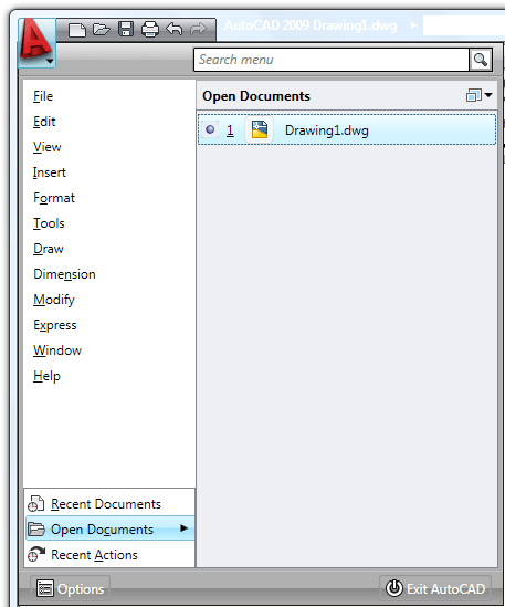
Click on the big red "A" button to open the Menu Browser.
![]()
Search for menu commands using the search field displayed at the top of the menu browser. Search results can include menu commands, basic tooltips, command prompt text strings, or tags.
By using tags, you can group commands according to your drawing needs. For example, a group of menu commands that you use frequently for a particular project can be assigned a tag named for that project. To create and edit tags, open the Tag Editor in the Customize User Interface dialog box.
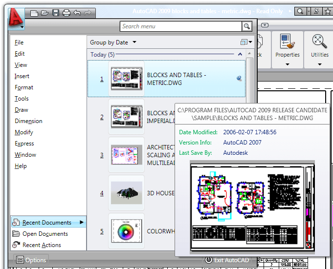
You can view recently used files and menu commands in the menu browser. You can also view a list of open files. The Recent Documents, Open Documents, and Recent Actions views are available at the bottom below the menus.
Click the push pin icon to keep a file available to view in the list regardless of files that may be saved later.
Recent documents show thumbnails, date modified, version info, last saved by, and currently opened by.
You can group recent files by date or type.
Recent Actions show recently performed actions such as file>open, tools>options for playback.
- Quick Access Toolbar
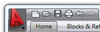
To the right of the big "A" is the Quick Access Toolbar (QAT).
On the Quick Access toolbar, you can store commands that you frequently use.
Right-click the Quick Access toolbar and click Customize Quick Access Toolbar. The Customize User Interface dialog opens and displays the list of commands available.
Drag commands you want to add from the command list pane in the Customize User Interface dialog box to the Quick Access toolbar.
If you right-click on QAT you have the option to show or hide the classic menu bar.
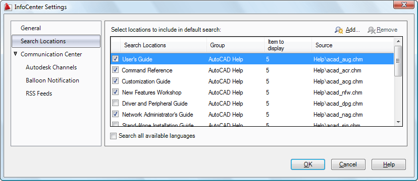
- InfoCenter
The top of the application window displays InfoCenter, Communication Center and Favorites. The new is that the InfoCenter box can be hidden by clicking on the arrow to the left of it. This will make more room to show the full path of the current drawing to the left of it.
![]()
When searching the AutoCAD help system for a topic, you can specify which document to search, decreasing the amount of time you spend trying to locate a topic.
InfoCenter Search Bar connects searches directly into Autodesk knowledge base and forums.
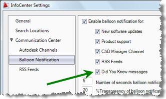
One new setting in InfoCenter Settings is the options "Did You Know messages" as balloon notifications.
- Ribbon
The Ribbon provides a single, compact placement for operations that are relevant to the current workspace. It eliminates the need to display multiple toolbars, reducing clutter in the application window. The Ribbon maximizes the area available for work using a single compact interface.
The Ribbon can be toggled to "minimize to panel titles", "minimize to tabs" and "show full Ribbon". With RibbonClose command the Ribbon can be be completely hidden.
The Ribbon provides easy access to AutoCAD tools through a collection of tabs and panels. Each tab contains multiple panels, and each panel contains multiple tools. Some panels can be expanded to access additional tools.
The Ribbon can be displayed horizontally, vertically, or as a floating palette. The horizontal Ribbon is displayed at the top of the drawing window by default when you create or open a drawing.
Drag individual Ribbon panels into the drawing window to create floating panels. When you select another tab on the Ribbon, the floating panels do not display until you select their associated tab again.
The Ribbon can easily be customized. You can create your own panels to display on the Ribbon; you can also modify the commands and controls on existing Ribbon panels.
To create or modify a Ribbon panel, use the Customize User Interface Editor (Customizations In <file name> pane, Ribbon Panels node). When working with Ribbon panels, you can create new rows or sub-panels to organize commands and controls. You use a panel separator to control which rows are always displayed. The rows above the panel separator are always displayed; those below are displayed only when the panel is expanded.
After you create or modify a panel, you can display the panel on a Ribbon tab. Ribbon tabs are used to group similar Ribbon panels. To display a Ribbon tab on the Ribbon, use the Workspace Contents pane in the Customize User Interface Editor to modify which Ribbon tabs are displayed when a workspace is set current.
- Quick Properties
The Quick Properties panel displays the commonly used properties for each object type, thus making them easier to find and improving access to them.
With the Quick Properties panel, you can edit properties for a selected object, or for all objects in a selection.
The Quick Properties panel is displayed when you select a single object or multiple objects in your drawing. You can set where you want the Quick Properties panel to display. You can change the value of the QPLOCATION system variable or you can select a mode in the Quick Properties panel shortcut menu.
The location modes for the Quick Properties panel are cursor and float.
Cursor is the default location mode of the Quick Properties panel. In cursor mode, the Quick Properties panel is displayed in a location relative to where you selected the object.
In float mode, the Quick Properties panel is always displayed in the same position unless you relocate the panel manually.
You can customize the contents of the Quick Properties panel for every object type.
- Quick View tool
With the Quick View tool, you can preview and switch between open drawings and layouts in a drawing by displaying them in a two-level structure.
You can increase or decrease the size of the layout preview images by holding down the Ctrl key while rolling the mouse wheel up or down.
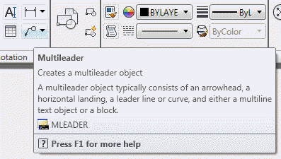
- Extended tooltips
Tooltips have been enhanced and now include two levels of content: basic and extended. When you initially hover the cursor over a command or control, the basic tooltip is displayed. It contains a general description of the command or control, the command name, shortcut keys, and command tags.
Extended tooltips are displayed after the cursor hovers over a command or control for a defined increment of time. You set the time increment in the Options dialog box.
Extended tooltips provide additional information about a command or control and can show a graphic illustration.
You can add extended tooltip information to your custom commands with the Customization User Interface editor.
- Status Bar
The AutoCAD status bar has been updated with new tools and icons. A right-click menu enables you to easily switch the Status bar display from icons to traditional text labels and back. The Quick Properties (QP) toggle is a new addition to the Status bar.
The Model and Layout buttons have been moved to the right side of the Status bar, where several new tools have also been added. The Layout flyout has been replaced by the Quick View Layouts button, which is accompanied by the Quick View Drawings button. The Status bar provides easy access to navigation and viewing tools, including Pan and Zoom, as well as the new SteeringWheels™ and ShowMotion™ functionality. The Annotation Scale has been replaced with a Viewport/Annotation toggle that links the annotation scale to the viewport scale, helping to ensure that they stay in sync. A new Workspace Switching button replaces the Workspaces toolbar, providing the same functionality in considerably less space.
Action Recorder
You can create an “action” macro and record a series of commands and input values and then playback the macro later. With the Action Recorder, you can easily create macros; this process does not require any programming experience.
You can insert a message in an action macro that displays during playback and you can change a recorded value to request a new value during playback.
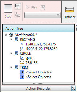
Each action macro that you create is saved as an individual file and stored in the location specified by the Action Recording File Location option on the Files tab of the Options dialog box. You can easily share your action recordings or use those created by others by including the shared path in the Additional Actions Reading File Locations list.
Caveat is that this feature is very basic to say the least. There are a lot of limitations. Here is a good blog post describing some of it.
Viewing Tools
- SteeringWheels
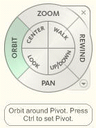 SteeringWheels are menus that track the cursor over the drawing window, and provide access to 2D and 3D navigation tools from a single interface.
SteeringWheels, or “wheels,” are divided into wedges; each wedge contains a single navigation tool. You can start a navigation tool by clicking a wedge or by clicking and dragging the cursor over a wedge.
There are four different wheels that are available. Each wheel has its own navigation theme.
-2D Navigation Wheel – Navigate a model by panning and zooming.
-View Object Wheel – Center a model and define the pivot point to use with the Orbit tool. Zoom and orbit a model.
-Tour Building Wheel – Navigate a model by moving towards or away, looking around, and changing the elevation of a view for a model.
-Full Navigation Wheel – Center a model and define the pivot point to use with the Orbit tool; walk and look around; change the elevation of a view; orbit, pan, and zoom a model.
As you navigate a model with the tools on the wheels, the previous views are saved to the navigation history for the model. To restore a view from the navigation history you use the Rewind tool.
- ViewCube
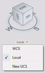 The ViewCube provides visual feedback about the current orientation of a model. The ViewCube can help you adjust the viewpoint of a model. The orientation shown by the ViewCube is based on the North direction of the WCS for the model. The ViewCube also shows the current UCS and allows you to restore a named UCS.
The ViewCube uses labels along with a compass to indicate the direction from which you are viewing a model. You can click both the compass and surface of the ViewCube to change the viewpoint of a model. You can change the current viewpoint of the model by clicking on the surface of the ViewCube, or the orthographic triangles and roll arrows located around the ViewCube.
You can use the ViewCube to change the viewpoint of the model, but you can also change the view projection of a model, define and restore the Home view for a model, and restore a named UCS saved with a model.
Allows you to switch between standard and isometric views.
- ShowMotion
With ShowMotion, you can access named views that are stored in the current drawing and that are organized into categories of animated sequences.
These sequences can be used to create presentations and to review designs.
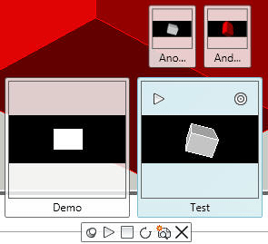
Each category of animated sequences is displayed as a thumbnail in the ShowMotion panel. The views in each category are also displayed as thumbnails. With the thumbnails, you can find, view, and modify animated sequences.
The animated views created through ShowMotion are known as Shots. They can be modified through the View / Shot Properties dialog box.
From the Shot Properties tab within this dialog box, you can adjust transitions between views. The type of movement, the position of the camera, and the length of recording can also be changed.
However, the options available on the Shot Properties tab depend on which view type has been selected. For example, if the view type of a Shot is Still, the length of the recording can be changed, but not the position of the camera. This is not the case when the selected view type is Cinematic or Recorded Walk. Different options appear for each view type.

Geographic Location
Geographic location embeds location-specific references – expressed as real-world coordinates (X,Y, and Z) – in your drawing.
You can then send your georeferenced drawing for review.
For example, you can:
-Put the drawing on a map (using AutoCAD Map 3D)
-See your design in the landscape (using AutoCAD)
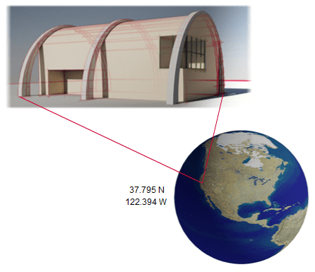
When geographic location information is embedded in a drawing, a geographic marker —visual representation of location information — is created.
You can include geographic location information in the following ways:
-Import a KML / KMZ file that has the location information
-Import a location from Google Earth.
-Manually enter the location values.
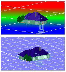
The geographic marker is displayed differently in 2D and 3D.
Note: To view the geographic marker, set the GEOMARKERVISIBILITY system variable to 1.
DWFx
DWFx — the future of DWF — is based upon the XML Paper Specification (XPS) format from Microsoft.
You can view and print DWFx files using Internet Explorer 7 on Windows Vista and Windows XP.
You can now – plot or publish to DWFx, attach DWFx files as Underlays, and read DWFx files using Markup Set Manager.
You can attach DWFx files as an Underlay and you can read a DWFx file using Markup Set Manager.
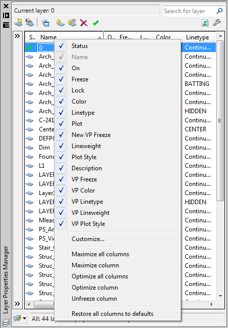
Enhanced Layer Properties Manager
The new layer dialog box is mode-less just like the Properties palette.
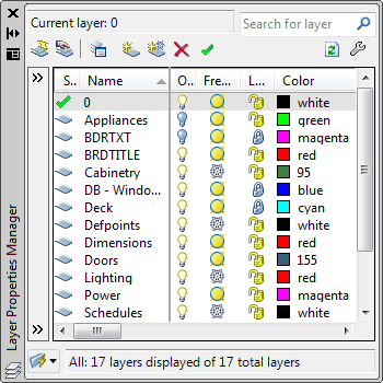
Layer property changes are now applied instantly. You do not need to click Apply or OK to apply changes.
When space (Model to Layout or Layout to Viewport) is switched, the enhanced Layer Properties Manager displays the current state of the layer properties and filter selection in the current space. The display of the appropriate additional layout or viewport properties is restored.
The enhanced Layer Properties Manager supports dual monitor scenarios. It can be placed on secondary display while drafting on primary display. Therefore, the drawing editor is uncluttered and organized.
The dialog box can also be minimized or closed when not needed.
You can now use layer filters in real time. Filter selection is instantly reflected in the drawing session.
With the Hide/Show Layer Filters pane button, you can now control the display of the layer filters pane in the Layer Properties Manager.
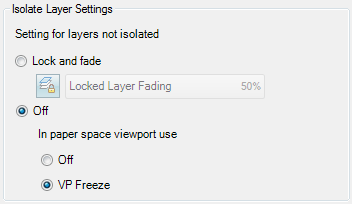
Layer Isolate controls have been added to the Layer Settings dialog box.
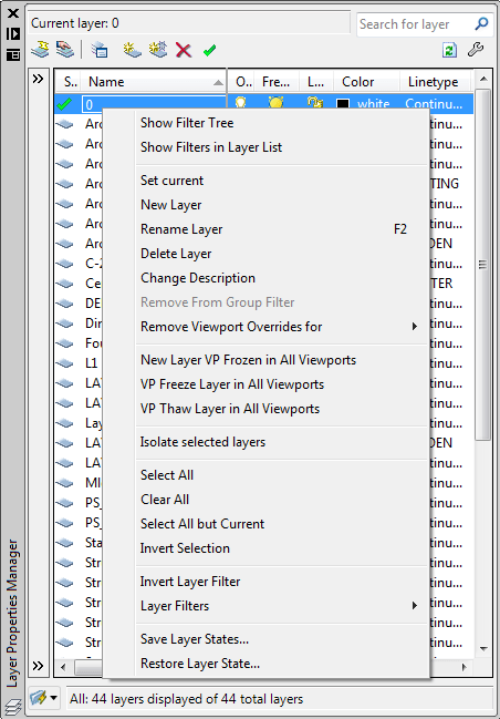
The context menu has been expanded to include "Remove Viewport Overrides for" and "Isolate selected layers"
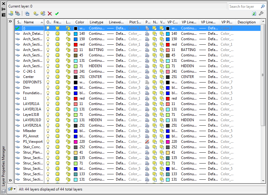
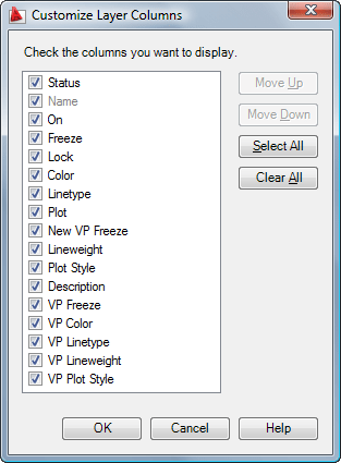
Columns can be customized. Select what columns you want to see or not. Change the column width using the Maximize and Optimize options on one column at a time or on all. You can also freeze/unfreeze a column like in Excel so the columns of your choice always are seen on the left side.
Customize Layer Columns dialog box.
A new option for combining layer property changes for Undo and Redo operations is accessible from the User Preferences tab of the Options dialog box.
Layers are sorted differently in AutoCAD 2009. In previous versions 10 was sorted before 2, 20 before 9 and 02 before 1. Not any longer.
Hidden message settings
You can selectively restore hidden messages using a new option on the Systems tab of the Options dialog boxes.
DGN support
Exporting AutoCAD DWG files to Bentley Systems’ MicroStation® V7 DGN format.
Control the layer visibility of attached DGN files by selecting the DGN Layer option from the right-click menu when a DGN attachment is selected.
DGN mapping tool (command DGNMAPPING) enables you to map DGN levels, linestyles, lineweights, and colors to AutoCAD layers, linetypes, lineweight, and colors, and vice versa. Save and access named DGN mappings for increased control during the import and export of DGN files.
Xref Clipping
Use grips to edit the boundary of a clipped external reference or block. Ensure the XCLIPFRAME system variable is set to 1, and select the clipped xref and grab a grip. More about this here with a tip to make the frame not plot.
Interactive Array Preview
While previewing of an array of objects from the Array command, you can pan, zoom, and navigate the model before accepting the newly arrayed objects.
Find and Replace
Find and Replace text in blocks and in Xrefs.
The Find and Replace include an expandable dialog box and more options.
Lists results in a table displaying the text location (model or paper space, for example), object type, and text string where the text was found. The resulting table can be sorted by column.
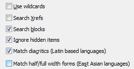
- Use Wildcards
Allows the use of wild-card characters in searches. - Search XRefs
Includes text in externally referenced files in search results. - Search Blocks
Includes text in blocks in search results. - Ignore Hidden Items
Ignores hidden items in search results. Hidden items include text on layers that are frozen or turned off, text in block attributes created in invisible mode, and text in visibility states within dynamic blocks. - Match Diacritics (Latin-based languages)
Matches diacritical marks, or accents, in search results. - Match Half/Full Width Forms (East Asian Languages)
Matches half- and full-width characters in search results.
Zoom to found text in different coordinate systems works now. Bugfix.
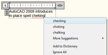
Spell checking
In-place spell checking is working for both text and mtext.
Mtext
- Pressing Escape key during Mtext now prompts for option to save mtext input
- New variable to control mtext table toolbar to display as fixed, floating, or in the ribbon
Lighting
A new value in the VSLIGHTINGQUALITY system variable offers more control over the lighting quality in the current viewport. You can now set the value to 2 for per-pixel lighting.
Network license
Prior version support is the new thing for the 2009 productswhen it comes to network licensing. When new licenses are generated for subscription customers the license file will allow the current and three past versions to run.
Export layout
Exports all visible objects from current layout to the model space of a new drawing.
Background command
Sets up the background for your view. Each view can have a separate background.
Hide and Show Palettes
Using the HIDEPALETTES and SHOWPALETTES commands you can hide and show all palettes. The ribbon is also treated as a palette. SHOWPALETTESTATE variable indicates whether palettes were hidden by the HIDEPALETTES command or restored by the SHOWPALETTES command.
eTransmit
Now with option to save or not to save a drawing before continuing with the command. Purge drawings is added as action. Does a complete purge of all the drawings in the transmittal package. Nested items are purged. Regapps are not purged.
Nonrectangular Viewports in Properties
Before both the viewport and polyline showed up. Now only the viewport is available in the properties palette.
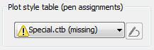
Missing plot style table
A warning symbol shows up if a plot style table is missing.
Missing plotters
This AutoCAD Warning does no longer show up if a PC3 file or plotter is missing on your computer: "Sample.pc3: This plotter configuration cannot be used for one of these reasons: the driver cannot be found, the device cannot be found, or the driver has a problem. The None plot device has been substituted."
In the Plot dialog, if a plotter device is missing, the indication of the word “Missing” is now prefixed in the plotter device name instead of being suffixed. This avoids the possibility of not knowing the device is missing since the plotter name may get truncated in the Plotter Name text box especially if the Plotter name is long.
Text Find toolbar
![]()
Materials
- Option to fit Gizmo to Object
- Can now Fit Mapping to Gizmo for material map scale
- Gradient Ramp procedural map
Blocks
Selecting a block or dynamic block and then typing “W” will invoke the Wblock command and the selected block’s name will be listed in the source text box.
Purge
Shortcut key for Close is now implemented in the Purge command
Other things new
Show Me animations are embedded into Help file.
It is now possible to click anywhere on a solid hatch to select it even though the selection preview doesn't show it.
Dwg files are now automatically locked on the Buzzsaw site when opened with AutoCAD.
New APIs available via .NET and ObjectARX
- User Interface enhancements
- Ribbon Bar, Menu Browser, Task Dialog, Tooltips
- Implemented using the Windows Presentation Foundation (WPF)
- Autodesk.Windows
- Quick Properties
- The feature uses existing static and dynamic COM properties for objects
- New COM interfaces for more control
- IFilterableProperty, IFilterablePropertySource, IFilterableMultiplePropertySource, IFilterableSubtypePropertySource
- Transient Graphics
- More flexible handling of all kinds of transient graphics
- Autodesk.AutoCAD.GraphicsInterface.TransientManager
- 3D Navigation
- Control over the new 3D navigation controls in AutoCAD
- ViewCube / Steering Wheel / ShowMotion
- ObjectARX-only
- Data Extraction
- Easily extract AutoCAD object properties
- Autodesk.AutoCAD.DataExtraction
- In-Place ActiveX Control
- Embed AutoCAD 2009 inside an ActiveX container. Usage of AcCtrl.dll is described here. Us in Web-page, Office document, WinForms application, etc.
- InfoCenter
- Enhanced InfoCenter API
- Autodesk.AutoCAD.Windows.InfoCenter
- Geo-Location
- Allows mapping of AutoCAD drawing units to read-world geography
- Autodesk.AutoCAD.DatabaseServices.GeoLocationData
- Material Map
- Opt out of using texture filtering during render
- Autodesk.AutoCAD.GraphicsInterface.MaterialMap
- Boundary Representation
- .NET wrapper for the ObjectARX API
- Autodesk.AutoCAD.BoundaryRepresentation
- Associative Dimensioning
- New API for an existing feature
- ObjectARX-only
- Permanent object deletion
- Allows actual deletion of erased objects
- ObjectARX-only
- New ObjectARX smart pointer
- Avoids open conflicts
- Allows optimized opening, returns existing opened objects
- Including open for write!
- Allows opening for write on Locked Layers
- AcDbSmartObjectPointer protocol-compatible with AcDbObjectPointer
- ObjectARX-only
- Avoids open conflicts
- New events & reactors
- Many new notifications, including:
- A nnotation Scale, Regen, ViewCube, Steering Wheel, Ribbon events...
- ObjectARX SDK for AutoCAD 2009 includes a brand-new AutoCAD .NET Reference
Autodesk Design Review 2009 (optional install)
System Requirements
Microsoft® Windows Vista™, Windows XP Professional or Home Edition (SP2 recommended), Windows 2000 SP4
Microsoft® Internet Explorer 6 (SP2 recommended) or later
800 MHz 32-bit (x86) or 64-bit (x64) processor (faster processor recommended)
512 MB RAM (for Microsoft Windows Vista users, 1 GB RAM or more recommended)
150 MB free disk space for installation
1024 x 768 VGA
Mouse, trackball, or compatible pointing device
CD-ROM drive, DVD-ROM drive for 64-bit systems
Optional Hardware:
3Dconnexion SpaceTraveler™ support for 2D and 3D navigation
GPS device set to communicate using NMEA 0183 standards, the standard 4800 baud rate, and a COM Port (COM1 to COM10). This includes:
GPS device bundled with Microsoft Streets and Trips 2006
Panasonic Toughbook® with integrated GPS device
USB connected GPS device
Bluetooth connected GPS device set to use a COM port
Note: If your computer does not meet these requirements, uninstall Design Review.
What's New?
Freewheel. Share DWF files on the Autodesk Labs Project Freewheel Web site using the ShareNow plug-in: http://freewheel.labs.autodesk.com/index.aspx. (Available in English only)
Find:
Find text. Locate text in an open file within Design Review.
Find Parts in an assembly. Quickly identify a specific part in a complex assembly.
Rotate 2D sheets prior to adding markup.
DWFx is the new default file format for Autodesk Design Review 2009. Team members using Microsoft Windows Vista can view 2D DWFx files without installing any software.
Enhanced user interface allows more user customization. Palettes can be grouped, docked, and pinned. Create customized layouts that best suit the needs of your team.
View 3D flexible components published by Autodesk Inventor.
Batch Print functionality no longer requires a separate downloaded plug-in.
Known Issues
The DGN and JT plug-ins can be downloaded from the Design Review plug-ins Web site: http://www.autodesk.com/dwf-plugins. For each plug-in, the associated README contains installation and usage instructions.
Installation of Autodesk Design Review 2009 requires local machine administrator privileges. Non-admin install is not supported.
If, when uninstalling Design Review, the Cancel button is clicked, the uninstallation will terminate but Design Review may not function properly. Solution: From the Windows Add or Remove Programs control panel, click Autodesk Design Review in the list to select it. Click Change/Remove to open the Autodesk Design Review Installation Wizard. Click Repair or Reinstall. Choose the Reinstall option and click Next. Follow the prompts to reinstall Design Review.
When Design Review 2009 is installed before DWF Viewer 7, double-clicking a file to open it causes DWF Viewer to launch. This happens because the most recently installed program assumes the DWF file association. Solution: To set Design Review 2009 as the default viewer, uninstall both DWF Viewer 7 and Design Review, and then reinstall DWF Viewer 7 before reinstalling Design Review 2009.
When AutoCAD 2007 is installed after Design Review, some system files are overwritten by the AutoCAD installation causing DWF shell extensions to fail. Solution: Uninstall and reinstall Design Review to restore the DWF shell extensions.
Publishing a DWF file from AutoCAD 2008 that consists of a single section and has password protection enabled may result in a DWF file that is corrupted and not usable.
Search Online may not function as expected in non-English versions of Design Review. This feature does not support double-byte or accented characters, or non-single byte property names.
Find (from the Find palette or the Find and Help toolbar) may fail to return any results if the DWF file was created using the DWF Writer. When possible, always use your design program's Publish command rather than using DWF Writer to convert DWG files, for example, to DWF files.
By design, Named Views in 3D DWG files are not published to DWF files.
Platform (Windows Vista, Windows XP, Windows 2000)
On Windows Vista systems, when the Windows Vista theme (Aero) is enabled, some DWF file layers may not be displayed as expected. Additionally, rotated 2D sheets may not be displayed correctly with this theme enabled. Solution: Right click the Windows desktop and choose Personalize. In the Personalization dialog box, click Theme. From the Theme drop-down list choose Windows Classic and click OK.
On Windows Vista systems, when embedding a DWF file in a Microsoft Office 2007 file, the Autodesk DWF Viewer Control is not listed in the Object dialog box (Insert > Object). Solution: In the Object dialog box, click Create New and, from the Object Type list, choose Autodesk DWF Document. Click OK to insert the embedded viewer.
If Design Review was used by a person with a Standard or Restricted user account, when a person with an Administrator user account uninstalls Design Review, two files (ActiveConfig.xml and woof_toolformats.xml) may not be uninstalled automatically. Solution: Manually delete the two files from the C:\Documents and Settings\[user name]\Application Data\Autodesk\Autodesk Design Review\9.0\userdata folder.
To save a file with a non-English file name, choose File > Save As, then right-click the Language Bar and start the Microsoft Global Input Method Editor (IME). Type the desired file name in the Save As dialog box and press Enter, after typing the file name, to exit the IME. Click the Save button or press Enter again to save the file.
On 64-bit systems, importing DWG or DXF files created in AutoCAD 2009 into Design Review 2009 may fail if DWG TrueView 2009 is installed. Solution: Use the Publish command in AutoCAD 2009 to publish the file to DWF.
Embedded
When viewing a DWF file embedded in Microsoft Internet Explorer (version 6 or 7), choosing Window > Workspace > Default, after one or more palettes have been displayed and unpinned, may cause Design Review to close unexpectedly.
When viewing DWF files embedded in Microsoft Office 2007 programs, a Customer Error Report (CER) dialog may not be displayed if the embedded viewer closes unexpectedly.
When saving a Microsoft Word 2003 or 2007 file after modifying an embedded DWF file, Autodesk Design Review prompts you to save the changes to the DWF file. When saving the Word file again, after subsequent modification to the embedded DWF file, you will not be prompted by Design Review to save the DWF file.
In Microsoft Office 2003 programs, when embedding a DWF file using the Insert > Object > Create New method, two Autodesk controls may be available in the Object Type list. Solution: Choose Autodesk DWF Viewer Control and click OK to insert the embedded viewer. Choosing any other "Autodesk..." Object Type will fail to properly embed the DWF file.
Dragging and dropping a sheet from the Thumbnails or List View palette in Design Review into Internet Explorer 7 may cause the Temporary Files (C:\Windows\Temp) folder to open.
DWF files embedded in Microsoft Word or PowerPoint 2003 files, when inactive, may be represented by a large generic DWF icon, rather than a thumbnail image of the DWF file content.
If a computer has the Update for Internet Explorer for Windows XP Service Pack 2 (KB912945) installed, Internet Explorer's script debugging must be disabled. Solution: In Internet Explorer, choose Tools > Internet Options. On the Advanced tab, under Browsing, verify that both Disable Script Debugging (Internet Explorer) and Disable Script Debugging (Other) options are checked. Click OK.
Display
If your computer is experiencing display issues as you view 3D DWF files, update your computer with the latest video card drivers. If you continue to experience display issues, choose Tools > Options and, on the Model tab, under View Settings, select a different setting from the Driver drop-down list.
On some computers, 3D DWF files may not be correctly displayed when the Video Card Driver is set to Direct3D. Solution: Choose Tools > Options. On the Model tab, under View Settings, from the Driver drop-down list select OpenGL.
Textures or surface bitmaps may not display properly in some 3D DWF files.
Depending on the settings used when publishing a 3D DWF file, choosing View > Standard Views > Shaded with Edges may not display all object edges distinctly. Solution: Choose Tools > Options. On the Model tab, under Color Settings uncheck the As Published option, and set a new Model Edge Color.
Dragging and dropping some raster images in the Thumbnails or List View palettes or on the Canvas may cause Design Review to stop responding. Solution: Convert the image to a different file type.
Large DWF files published from Autodesk Civil 3D or Autodesk Map 3D may contain dots that obscure geometry on the Canvas.
2D sheets or images that have been rotated and saved in Design Review 2009 may not be displayed properly when viewed in Design Review 2008.
Merging multiple DWF files by dragging and dropping into the List View or Thumbnails palette may result in the sheets being listed in no apparent order.
DWFx
When opening DWFx files saved in Design Review 2008, Microsoft’s XPS Viewer only shows 2D content. Non-2D content, such as 3D models or BOM tables, is indicated in the DWFx file by a single DWFx logo proxy page. Solution: To view the entire contents, open the DWFx file in Design Review.
Saving a very large DWF file, such as one that contains several hundred sheets, as a DWFx file may cause errors that result in a failure to save the file as DWFx.
When viewed in the Microsoft XPS Viewer, the object properties stored in DWFx files are not shown. Although not shown, the object properties remain available in the DWFx file when viewed in Design Review.
Printing and Batch Printing
To use the Batch Print Wizard, you must first open any DWF file in Design Review.
Printing a saved batch print job that failed to print earlier may trigger a Customer Error Report (CER) and cause Design Review to close unexpectedly.
When batch printing several sequential sheets that have been saved as separate DWF files, some sheets may not be printed in the order they are displayed in the Select DWF Files to Print dialog box.
Printing or plotting of large files may cause Design Review to close unexpectedly.
Right-clicking a file in Windows Explorer and choosing Print may fail to print the file if Autodesk DWF Viewer was installed after Design Review. Solution: Manually change the file association. Right-click the DWF file and choose Properties. In the file Properties dialog box, on the General tab, click the Change button to display the Open With dialog box. From the list of Recommended Programs, choose Autodesk Design Review. Or, if necessary, click Browse to navigate to and select DesignReview.exe on your system. Click OK to set the file association. Click OK again to accept the change and close the file Properties dialog box.
In the Batch Print Wizard, when selecting a password-protected DWF file, you are prompted for the file's password three times during the batch printing process.
Printing of fill patterns fails on some printers.
Measure and Markup
Georeferenced maps published with non-Cartesian coordinate systems cannot be measured.
When the computer user name contains double-byte characters, saving a 2D DWF file after creating markup causes a "File save failed" error. Solution: Create a new user profile where the user name contains only single-byte characters or change your user name using only single-byte characters.
In multi-sheet DWF files with marked-up 3D models, clicking a 3D markup in the Markups palette displays the model with the markup selected and the Orbit tool enabled rather than the Select tool. Solution: On the Main toolbar, click the Select tool to interact with the selected 3D markup callout.
In 2D DWF files that contain more than one viewport, measurements created within one viewport may be inconsistent with measurements created in another viewport.
When markup is deleted from a 2D sheet, the Rotate Sheet tool is available. Some markups, such as Freehand or Shape markups, must be deleted from the Canvas and then deleted from the Markups palette to (re)enable the Rotate Sheet tool.
Callout markups on 3D sheets cannot contain bold text.
Version Compare
Multiple sheets cannot be compared at the same time.
When comparing DWF file content to DWFx file content, the comparison results may contain false differences.
ActiveX API
The following outlines the additions and changes made to the ActiveX API in AutoCAD 2009 and AutoCAD 2009-based products.
Classes
IAcadUnderlay3 (New)
        DWFFormat - Property
IAcadWipeout (New)
IAcadUtility2 (New)
        GetSubEntity32 - Method
        ObjectId32ToObjectIdString - Method
        GetObjectIdString - Method
IAcadToolbarItem2 (New)
        CommandDisplayName - Property
Still missing
Still missing. Wish list for the next time.
VSTA support.
Saveall command should respect the Options setting to save in another version.
Using fence it would be possible to select an object with a linetype with spaces when the fence is hitting the space in the linetype.
Preview handler for Vista and Outlook 2007.
XCLIPFRAME=2 that is visible but does not plot.
Add and remove vertex points on the xref clipping boundary.
After using FIND and you zoomed to the location for what you search for it would be good if you have the option to staythere after you exit the command. Workaround is to use zoom previous after the FIND command.
If the External References palette is hidden and you run the XREF command it should show just like if you run the PROPERTIES command or as it did in AutoCAD 2008. There should at least be an option or a separate command that makes it roll-out.
In Quick Access Toolbar (QAT) there is undo and redo but the history is missing. It would be good to be able to place controls like the layer control as well in QAT.
3D navigation tool work in wireframe mode.
Right click on Ribbon and end up at the correct location in CUI.
XREFCLOSE command to be able to close the External References palette.
Transparency on ToolTips and Quick Properties.
Ability to specify the order of the items seen in Quick Properties.
Mspace and pspace toggle button on status bar should be visible even if the layout and model tabs are hidden.
Be able to dock the command line just like a toolbar or dock to the ribbon in a way that it is always visible no matter what tab is active.
In sheet set manager it used to work adding the Unicode \U+000A to force a new line (line feed) in properties so it showed on say two lines on the drawing. Now it gives a new line using SHX fonts and nothing at all with TTF fonts.
Make it as easy to select gradient hatches as it is to select solid hatches.
Add support to find solid and gradient hatches with the Matchprop command as easily as you can with the Erase command and solid hatches.
If you have a select object command like Erase and move it over a solid hatch it is not always showing that the object is selectable (selection preview) even though it is if you try to click on it.
In the menu browser it would be good if the groups in Recent Documents also remembered the state of collapsed and expanded.
Existing bugs
Existing bugs, defects, feature limitation or other issues.
Document "drawing.dwg" has a command in progress.
If SDI=1 and if you hold down the right mouse button while drag and drop a drawing from Explorer into AutoCAD so you get the right-click menu and select the Open option the drawing will not be opened, it will be inserted.
While in the Open dialog box I have got a crash with this message: "AutoCAD Error Aborting -FATAL ERROR: Unhandled Access Violation Writing 0x1bb007cc Exception at 77cd2e7bh"
In VBA this will fail: ThisDrawing.Application.Preferences.User.HyperlinkDisplayTooltip = False with Run-time error '-2147467259 (80004005)': Method 'HyperlinkDisplayTooltip' of object 'IAcadPreferencesUser' failed
getfiled bug hangs AutoCAD (probably related to Windows Vista) See this post.
SSM: Renaming the layout on a drawing breaks the hyperlinks in the Sheet List Table to the Sheet in question. Make a DWFx of it and try to follow the link.
SSM: Sometimes it is impossible to access "Recent" sheet sets as the list collapses as soon as you move the mouse.
When moving a clipped xref the objects outside the clipping shows up. This didn't happen in AutoCAD 2005.
Adding \X before <> on an arc dimensions make the arc sign double in size and the measurement disappears.
2004 introduced a bug (or change) when it comes to dimensions. The placement of alternate units are now above the dimension line. In 2002 it was below. "\X" doesn't help as primary unit suffix. But "\X " works as a workaround, observe the space after the X, change also the placement of the alternate units to be After the primary value.
Selecting multiple files in the opening dialog box and pressing enter doesn't work.
The Rename dialog box doesn't accept renaming of for example blocks with names including the # character.
Dimensioning with DIMSCALE set to 0 and using VPMAX doesn't work as expected. The scale of the viewport is not respected.
3DDWF cannot handle selection and deselection of objects within blocks and xrefs as good as it should. It should be possible to select the complete block or xref. It should be possible to deselect some objects within a block or xref after selecting everything using "all".
The Publish command sets the SAVETIME variable to 0 during its process. If AutoCAD crashes during the Publish command SAVETIME will not be restored. Workaround is to implicitly set SAVETIME in your startup lisp or VBA code.
3DCLIP and DVIEW using clip plans can result in just dots or no visible objects at all instead of lines. Workaround that sometimes work (try in a viewport from pspace) is to run the hide command. Typical case is if an object has both clipping plans clipping through it.
Dimension line is not correctly handled when stretching or moving only the text. If there is a vertical dimension and you stretch the text vertically the dimension line is moved horizontally a little too. But the second time you do it the dimension line is not moved. This also makes it hard to have alternate dimensions below the dimension line and the primary above.
+OPTIONS default value doesn't work correctly. Enter the command +OPTIONS and press enter you would suppose to get to the first tab but you comes to the second. To solve this you have to enter 0 as the Tab index to get it correct.
If you enter -30 for Obliquing of text it shows 330 in the properties or if you list it. But if you create a text style and enter 330 it reverts to -30. This is inconsistent.
When SDI=1 and opening subsequent drawings with xrefs the xref manager tray icon is not showed even though there are xrefs within the drawing.
dbConnect. Do not attach labels with zero-length leaders as they will not be updatable. If you do not want to see the leader line, use a freestanding label, not an attached label.
If a drawing contains the layer defpoints and is used to drag layers into other drawings the defpoints layer follows into the other drawing.
After publishing a sheet set to DWF or DWFx and I try to open it right clicking on the plot tray icon and selecting View DWF file I get the following error in Design Review 2009: "Your current version of Design Review does not support files of this type".
Publish to DWF or DWFx from SSM you will notice that the specify file dialog box does not show the list of files, just a blank window.
I got this once while publishing a sheet set to DWF: "AutoCAD Error Aborting - FATAL ERROR: Unhandled e06d7363h Exception at 7670b09eh".
I got this right clicking for properties on a sheet set in SSM: "AutoCAD Error Aborting - FATAL ERROR: Unhandled Access Violation Reading 0x137a6fcc Exception at 7700e2adh"
In some cases the trusted DWG icon in the status field can show up multiple times. Seems to be related to SDI=1.
Search within CUI is extremely slow.
Create an old-format polyline with PLINEGEN=1 and PLINETYPE=0 and you will not be able to snap to it. Workaround is to convert the polyline to the new format or to change PLINEGEN to 0 or using properties palette or the Pedit command to disable continuous linetype generation for existing objects. But this might still not work if the polyline has a width like a donut for example. (Probably fixed in Update 1)
If DTEXTED=1 and you create text with DTEXT command and hold down Shift and press the spacebar it is ignored.
I have run into times when the Quick Access Toolbar is missing. The workaround to restore it is to reset the profile in Options. It might help with this solution as well. (If you reset your profile you loose a lot of information (if you have actually customized it.) You don't actually have to reset the whole profile, just change your workspace. )
InfoCenter has a link to the RSS feed for the AutoCAD 2008 discussion group.
http://www.autodesk.com/rss-autocad2008forums
but it should be
http://discussion.autodesk.com/rss/rssmessages.jspa?forumID=344
dispsilh is not working on objects in xrefs.
Converting toolbars with nested flyouts to Ribbon panels in CUI you are in trouble. Ribbon does not support nested flyouts.
Performance problems with the layer palette and working with viewports.
Performance can be a problem if you want to change a lot of layers because the changes are made directly without exiting the layer manager.
If you migrate your settings from an older version the Quick Access Toolbar (QAT) might end up empty.
Ribbon panels changes size in an unexpected way by just selecting objects. Example is if the Home tab is visible the Layers and Properties panels expand a little.
Preview of TGA images in the Background command are rotated 90 degrees.
Quick Properties location is not correct if Windows DPI is not the default 96 dpi. This can result in having Quick Properties show up outside the screen.
M2P is the only osnap related command that does not pause a menu macro
or lisp (command pause) until the required point has been acquired. (old bug)
If you copy any object from one drawing to another where in the drawing you copy from includes annotation scales not in the other drawing these are copied as well even though they are not applied to the copied objects.
The following commands exists but are still unknown. Try for example enter -QV and press tab and you will get -QVDRAWING but it will say: "Unknown command "-QVDRAWING". Press F1 for help." The same for -NAVSMOTION, -QVLAYOUT.
There can be problems to publish to postscript printers.
I got this crash when editing the content of multiple mtext objects in Quick Properties: "AutoCAD Error Aborting- FATAL ERROR: Unhandled Access Violation Reading 0x6e650021 Exception at 5c477795h", "AutoCAD Error Aborting - FATAL ERROR: Unhandled Access Violation Reading 0xfffffff3 Exception at 712f59e2h" (Probably fixed in Update 1)
If PUBLISHCOLLATE is set to 0 it is not respected if you want a multi-page (multi-sheet) PDF using Page Setup Overrides in Sheet Set Manager using the the DWG To PDF.pc3. (Probably fixed in Update 1)
If PUBLISHCOLLATE is set to 1 and you create a multi-page PDF using DWG To PDF.pc3 I have found that in some cases characters are not plotted correctly using the PUBLISH command. Example was an A that was missing the horizontal line, but only one of the A's on the drawing. Another example was that part of a character was missing on one of the pages but seen on the following page. After testing further it seems like it is the last object or partial object that end up on the following sheet. Workaround is to either plot to DWF and then plot the DWF to PDF or to plot to single page PDFs and then combine them. (Probably fixed in Update 1)
If SDI=1 and you open a drawing using drag and drop from Explorer into AutoCAD by dropping it on the application top you crash AutoCAD with this message: "AutoCAD Error Aborting - FATAL ERROR: Unhandled Access Violation Reading 0x03dd Exception at a8d6c7h". (Fixed in Update 1) But it is fixed so you cannot drag and drop to open it this way at all.
When you attempt to display a tooltip of a multiline text (mtext) attribute that contains 281 characters or more, AutoCAD crashes. (Fixed in Update 1)
When you move a block using an insertion grip, mtext attributes move incorrectly. (Fixed in Update 1)
When the default value of an mtext attribute in a block contains a field, you cannot edit the attribute text to replace the field with other data. (Fixed in Update 1)
When a .NET function with a LispFunction attribute has the return type as object, an exception is thrown in AutoCAD. (Fixed in Update 1)
When you insert or redefine a block that contains attributes on a locked layer, AutoCAD crashes. (Fixed in Update 1)
When you change the scale of a block through the Properties Palette, an attribute displays incorrectly. (Fixed in Update 1)
Export a layout to model space has some bugs. The linetype scale changes. Dimension arrowheads do not display. Text does not rotate correctly. Drawing properties are lost. (Fixed in Update 1)
When you recreate a hatch boundary, it consists of separate line segments rather than a closed polyline. (Fixed in Update 1)
When you plot, objects in an xref are not correctly hidden. (Fixed in Update 1)
When you drag and drop a drawing while the In-Place Text Editor is active, AutoCAD crashes. (Fixed in Update 1)
When some of the values in the In-Place Text Editor are changed, AutoCAD crashes.(Fixed in Update 1)
Some mtext objects with double byte characters display as a single line. (Fixed in Update 1)
When you attempt to save a file with a long file name, AutoCAD may crash. (Fixed in Update 1)
When you attempt to open multiple files from Windows Explorer, only the first selected file opens. (Fixed in Update 1)
When the OPENPARTIAL system variable is set to 1, if you use the PURGE command, drawings may become corrupted. (Fixed in Update 1)
The AutoLISP Redraw function fails to hide or highlight objects. (Fixed in Update 1)
When you zoom while inserting some blocks, AutoCAD crashes. (Fixed in Update 1)
Annotation Scaling - A drawing that contains a large number of anonymous blocks and copies of annotative entities created in AutoCAD 2007, or an earlier release, opens slowly in AutoCAD 2009. (Fixed in Update 1)
Annotation Scaling - A scale is infinitely enumerated when you insert a drawing that contains the same scale as a block or an external reference (xref).
The External References palette ESW does not display when auto-hidden and used with the XREF or IMAGE commands are used. (Fixed in Update 1)
You cannot access the menu browser in a non-English version of AutoCAD using the shortcut Alt+Key. (Fixed in Update 1)
When created on a rotated UCS, a multileader does not respect POLAR or ORTHO settings. (Fixed in Update 1)
When you plot upside-down, an OLE object does not plot correctly. (Fixed in Update 1)
In the Properties palette, the Dimension Style control may display an incorrect dimension style name. (Fixed in Update 1)
In the Publish dialog box, the Publish To setting always defaults to DWF format even if you select a different setting. (Fixed in Update 1)
When you change the theme of your operating system while running AutoCAD and then click the Quick Properties window, AutoCAD crashes. (Fixed in Update 1)
When you open some valid drawings, you are prompted to use the RECOVER command. (Fixed in Update 1)
When you use the RENDER command with certain drawings that contain textured object, AutoCAD crashes. (Fixed in Update 1)
CUI problems below (Fixed in Update 1)
When acad.CUI is loaded as a partial CUI, some buttons in the multiline text (mtext) ribbon contextual tab fail.
On a ribbon panel, you may not be able to move items between rows.
A ribbon panel continues to display after it is removed from a ribbon tab.
A button image used on a ribbon panel that is loaded from a resource DLL file lacks a transparent background.
If you transfer a ribbon panel and a tab, buttons display small.
Enterprise, main, and partial CUI files display multiple ribbon tabs in workspaces.
You cannot control a ribbon tab when you use more than one non-AutoCAD CUI file.
A ribbon tab and/or menu macro may not function properly when referenced from multiple CUI files.
If you load a CUI file that references a missing BMP file, a fatal error displays.
Known Issues with Update 1:
After you apply this update, you may experience the following ribbon customization-related problems:
An Incorrect or Missing Ribbon Tab
Known Issue: When you display a ribbon tab from a partial of Enterprise CUI file, on the ribbon, the ribbon tab displays incorrectly or is missing.
Workaround: To correctly display a ribbon tab, recreate the workspace used to display the ribbon tab from scratch. Do not duplicate or attempt to update the workspace. Once you create a new workspace, set the workspace current. The ribbon tab should display correctly.
For a partial CUI file, before you add a ribbon tab to a workspace, use the Customize User Interface (CUI) Editor to change the customization group name of the file. The customization group name is represented by the uppermost node of the tree in the Customization In pane.
A Blank Image for a Command
Known Issue: On a ribbon panel, the image associated with a command defined in the Command List pane displays as a blank icon.
Workaround: To recreate a ribbon command item on a ribbon panel, delete it. Then, from the Command List pane, add the command to the ribbon panel.
Use this link to report a bug to Autodesk that bugs you: http://www.autodesk.com/submitbug
Removed
Removed.
The Dashboard is replaced with the Ribbon.
Tips & Tricks
Tips & Tricks
_VERNUM = "C.56.0 (UNICODE)"
Version 11.4.1 of the FlexNet license manager that ships with AutoCAD 2009-based products is backwards compatible and will administer licenses for the Autodesk 2008-, 2007-, 2006-, 2005-, 2004-, and 2002-based products as well as products from other vendors.
57600ACD_2009_0F is the FlexNet feature code for AutoCAD 2009.
The registry hack to change from SLM to NLM will not work completely with AutoCAD 2009 so if you have a standalone installation you need to uninstall completely before installing the network one if you also want the cascading functionality to work.
Shift+W is now hardcoded to launch the Steering Wheel and cannot be customized with CUI to do something else.
Set AutoCAD 2009 to look like AutoCAD 2008 see this blog post. Select the AutoCAD Classic workspace as a starter.
Do you want to run AutoCAD 2009 on Citrix? Only AutoCAD 2009 is not possible but AutoCAD Map 3D 2009 is Citrix Ready. Visit www.autodesk.com/citrix for details.
Make sure to install dictionaries as feature if you select a custom installation. Even if you don't need multi-language dictionaries you will get an annoying error message every time you want to create or edit text. "AutoCAD Message - Unable to find main dictionary. Could not start speller."
Seems like another undocumented command.
Command: CLIP-TAHOE+1
AutoCAD unified clip command goes here.
Readme
Readme
Installation, Configuration and Hardware
Installing from Dual CD/DVD ROM Drive Systems
Installation fails if you attempt to install AutoCAD 2009 installation discs in different drives of a dual CD/DVD ROM drive system. You must use the same disc drive in order to complete the installation process.
HTML Help Fails When Launched from a Network Drive
You cannot launch the Help System from a network drive. A "Page Cannot Be Displayed" warning is displayed. This limitation is a result of the Windows Security Update #896258 from Microsoft.
Running a Network License Manager on Microsoft Windows Vista
When starting the network version of AutoCAD 2009 on a Microsoft Windows Vista workstation, you may encounter licensing error -15 if the license manager is running on Windows Vista (FLEXlm server version 11.4.100). Do the following:
Install the latest Service Pack and updates for Microsoft Windows Vista.
If you continue to encounter errors, do the following:
On the Start menu (Windows Vista), click Control Panel Network and Sharing Center Manage Network Connections, right-click on Local Area Connection. Select Properties. Uncheck Internet Protocol 6 (TCP/IPv6). Click OK.
FlexLM License is Created in Two Locations
The FLEXlm License Finder dialog box may not display upon each launch of AutoCAD 2009 for non-administrative users who are using Windows Vista 64-bit. This is becuase the license server path information is stored in the HLKM\STOFTWARE\Wow6432Node path, which is not accessible to non-administrative users.
To fix this problem, replicate the license server path information stored in the above path to go to the HKLM\software\FLEXlm License Manager path.
Remote Access Applications
It is not recommended that you use any type of remote access application in conjunction with AutoCAD 2009 when it is configured to use hardware acceleration. Most remote access applications cannot support hardware acceleration, which can cause general display failure and instability. If you need to use remote access applications, disable hardware acceleration or use the /NOHARDWARE command line switch to start AutoCAD 2009 in Software mode.
Hardware Certification Database
To download and install the latest hardware certification XML file, visit the Hardware Certification website at http://www.autodesk.com/autocad-graphicscard.
Join the Customer Involvement Program
Here is a list of the information that is automatically sent to Autodesk:
Name and version of the Autodesk product
AutoCAD commands used, and amount of time spent in AutoCAD
Error conditions encountered, fatal, and non-fatal
File formats imported or exported with AutoCAD
Operating system name and version
System configuration information such as processor, amount of memory, and graphics card
IP address, used to identify your country or region
The Customer Involvement Program is committed to protecting your privacy. It cannot do any of the following:
Collect any drawing or design data
Collect any identity information such as name, address, or phone number
Send you email or contact you in any other way
For additional information, click the links in the Customer Involvement Program dialog box.
The Customer Involvement Program involves you directly in telling Autodesk
The commands and features that Autodesk should focus on
The commands and features that are hardly ever used
The most common problem areas
The hardware typically used with AutoCAD
Note. You can start or stop your participation in this program at any time. Access to the controls is available from the AutoCAD Help menu. In network installations, your system administrator can choose whether to make the CIP program available or not.
To turn the CIP on or off
Click Help menu > Customer Involvement Program.
In the Customer Involvement Program dialog box, click a level of participation, and then click OK.
Graphics Card Driver Update
You should verify and update your graphics card driver to optimize AutoCAD 2009. Use the following procedure to identify your current graphics card driver.
To identify your graphics card driver
Start AutoCAD 2009.
At the Command prompt, enter 3dconfig.
In the Adaptive Degradation and Performance Tuning dialog box, click View Tune Log.
Review the 3D Device section for information about your system's graphics card driver and driver version.
If you find that you do need to update your driver, visit http://www.autodesk.com/autocad-graphicscard to find a certified driver for your graphics card. If you do not find one, visit the graphics card manufacturer's website.
Note. If the graphics card manufacturer does not have an updated driver, check the system manufacturer's website. Companies like IBM, Hewlett Packard, and Dell often supply their own system drivers.
Draw and Edit
Tool Palettes
Tool palettes created in the current release should not be used in previous releases.
Plot and Publish DWF Files
AutoCAD 2009 for 64-bit halts unexpectedly when publishing DWF drawings containing text, multiline text (mtext), and attributes that use the CityBluePrint font. To repair this problem, download and install the Windows security update availalbe at http://www.microsoft.com/technet/security/Bulletin?MS06-002.mspx.
Opening Sample Drawing Files in Windows Vista
Due to Windows Vista restrictions, all sample files found in the AutoCAD 2009 Sample folder and subfolders are read-only. Sheet Set Manager sample files can be opened in the Sheet Set Manager, but cannot be changed.
Autodesk i-drop
For i-drop to operate properly on a system running Windows Vista, the user should be set to Run as Administrator.
3D Environment
AutoCAD 2007 introduced a new 3D Modeling environment, which you can access by means of the VISUALSTYLES command and choosing any non-2D style. The 3D environment has some behavioral differences when compared to the legacy 2D drafting environment, such as:
Draw order is not supported in 3D
Memory usage in 3D is higher
The REGEN and REGENALL commands do not necessarily clean up display artifacts. To reset the display, cycle VISUALSTYLES between 2D and non-2D styles.
Direct 3D with Microsoft Windows Vista
When Direct 3D is enabled in a Windows Vista environment, the cursor appears as black and white instead of color in non-2D visual styles. Any changes to the cursor from the Options dialog box are not enabled in this environment.
Animation and Rendering
Animation Output
The Quicktime Player cannot play MOV files saved with characters that are not native to the current operating system.
Windows Vista versions K and N (available in Korea and Europe) do not come with Windows Media Player installed. In order to use the animation feature in AutoCAD 2009, download the latest version of Media Player from the Microsoft website.
Advanced Render Settings
In the Advanced Render Settings Dialog box, the Memory Limit field is ignored in AutoCAD 2009 for 64-bit. AutoCAD 2009 will make use of all available memory in a 64-bit environment.
Other Drafting Issues
External References
Due to the external references (xref) polling cycle, you can encounter a time lag when attempting to use the Manage Xrefs icon to reload DWG xrefs. You cannot reload referenced DWG files with this method until you see the balloon notification on the Manage Xefs icon is displayed. To expedite the reloading process, use one of the following methods:
On the External References palette, right-click the reference drawing. Click Reload.
On the External References palette, click Reload All References.
At the Command prompt, enter -xref. Use the Reload option.
Text and Language
Multiple-Language Support
When you copy and paste characters that have been created using a language other than the system language, the characters may not be displayed correctly.
To correct the display to show the original language
Double-click the text to open it in the In-Place Text Editor.
Right-click inside the editor. Click Character Set and select the original language.
User Interface
Display AutoCAD as in Previous Releases
AutoCAD 2009 introduces a new look and many new user interfaces that change the way you access commands. To display AutoCAD 2009 as it was in previous releases, do one of the following:
Click the Menu Browser button > Click Tools > Workspaces > AutoCAD Classic.
On the status bar, click Workspace Switching > AutoCAD Classic.
Use Workspaces to Switch AutoCAD Interfaces
Workspaces are sets of menus, toolbars, palettes, and ribbon panels that are grouped and organized to create a task-oriented drawing environment. In addition to AutoCAD Classic, the following task-based workspaces are available in AutoCAD 2009:
2D Drafting & Annotation
Displays tools specific to 2D drafting. Displays the new interfaces, including the ribbon and menu browser.
3D Modeling
Displays tools specific to 3D modeling. Displays the new interfaces, including the ribbon, menu browser, and Tool Palettes window.
To switch between available workspaces, do one of the following:
Click the Menu Browser button > Click Tools > Click Workspaces and select the desired workspace.
On the status bar, click Workspace Switching and select the desired workspace.
On the Workspaces toolbar, in the Workspaces drop-down list, select the desired workspace.
Migrate CUI Files from a Previous Release to AutoCAD 2009
When loaded as the main CUI file, a CUI file created in a previous release of AutoCAD does not contain the necessary content to utilize new AutoCAD 2009 user interface elements. To add new user interface elements to an existing CUI file, do one of the following:
Use the Transfer tab in the Customize User Interface (CUI) Editor to transfer user interface elements from your CUI file from a previous release of AutoCAD to a new CUI file that comes with AutoCAD 2009. The new CUI file will allow you to use new user interface elements of AutoCAD 2009 while allowing you to use existing customization.
Use the Migrate Custom Settings dialog box to convert your CUI file from a previous release to a new version that will be compatible with AutoCAD 2009. To migrate CUI files and user profiles from the previous release, do the following:
Click Start menu (Windows) > Programs > Autodesk > AutoCAD 2009 > Migrate Custom Settings Migrate > From a Previous Release.
In the Migrate Custom Settings dialog box, in the Migrate Settings drop-down list, select the release that you are migrating from. Click OK.
Note. The Quick Access toolbar for any migrated workspaces will be empty. To display commands on the Quick Access toolbar, use the Customize User Interface (CUI) Editor. You cannot migrate dashboard control panels to the ribbon. You must recreate your dashboard control panels as ribbon panels using the Customize User Interface (CUI) Editor.
Developer Information
Changes That May Affect Scripts
Changes to the following commands or system variables may affect pre-existing scripts:
EXTEND
For the EXTEND command, if you do not select an object at the Select Objects to Extend prompt, you are now prompted to specify the opposite corner of a crossing window. This change may affect pre-existing scripts that call EXTEND and supply a pick point that selects no objects. You can fix legacy scripts by omitting points that do not select objects.
INSERT
If you use the Scale Uniformly option in the Block Definition dialog box, you are no longer prompted to enter separate scale factors for X,Y,Z coordinates when you insert a block using the -INSERT command.
MENULOAD
By default, the MENULOAD command loads only CUI files in AutoCAD 2006 or later releases. To load an MNU or MNS file in AutoCAD 2006 or later release, you must explicitly include the extension in the file name, as shown in the following example:
(command "menuload" "myMenu.mnu")
However, rather than changing your code, it is strongly recommended that you open your legacy menu files in AutoCAD 2009 before running applications that use them. AutoCAD 2009 automatically converts them to CUI files, and the CUI files are loaded by existing code that uses the file name without an extension
Legacy code that specifies an MNU, MNS, or MNC extension should be changed to reference a CUI file, and AutoCAD 2007-based applications should ship with CUI files, not MNU, MNS, or MNC files.
TRIM
For the TRIM command, if you do not select an object at the Select Objects to Trim prompt, you are now prompted to specify the opposite corner of a crossing window. This change may affect pre-existing scripts that call TRIM and supply a pick point that selects no objects. You can fix legacy scripts by omitting points that do not select objects.
ActiveX and VBA
VBA scripts that run at startup should check whether the AutoCAD 2009 process is visible or invisible. If the process is invisible, the script should not execute, because the process may be performing background plotting or publishing operations. To check whether the AutoCAD 2009 process is visible or invisible, you can use the Visible property of the Application object in the AutoCAD 2009 Object Model.
Quick Properties
To maximize performance when scripts or LISP rountines are run, the Quick Properities panel is disabled. Completion of the routine restores functionality.
System Requirements
Before you install AutoCAD 2009, make sure that your computer meets the minimum hardware and software requirements.
Whether the Windows operating system is the 32-bit or 64-bit version is automatically detected when installing AutoCAD 2009. The appropriate version of AutoCAD 2009 will be installed. The 32-bit version of AutoCAD 2009 cannot be installed on a 64-bit version of Windows.
.NET framework 3.0 is installed with AutoCAD 2009 but 3.5 works as well.
See the following tables for hardware and software requirements.
| Hardware and software requirements | ||
|---|---|---|
| Hardware/Software | Requirement | Notes |
|
Operating system |
32-bit Microsoft® Windows® Vista® Enterprise Microsoft Windows Vista Business Microsoft Windows Vista Ultimate Microsoft Windows Vista Home Premium Microsoft Windows XP Professional Edition (SP2) Microsoft Windows XP Home Edition (SP2) 64-bit Microsoft Windows Vista Enterprise Microsoft Windows Vista Business Microsoft Windows Vista Ultimate Microsoft Windows Vista Home Premium Microsoft Windows XP Professional Edition (SP2) |
It is recommended that non-English language versions of AutoCAD 2009 be installed on an operating system with a user interface language that matches the code page of the AutoCAD 2009 language. A code page provides support for character sets used in different languages. |
|
Web browser |
Microsoft Internet Explorer® 6.0 SP1 or later |
You cannot install AutoCAD 2009 if Microsoft Internet Explorer 6.0 SP1 (or later) is not installed on the installation workstation. You can download Microsoft Internet Explorer from the Microsoft website: www.microsoft.com/ |
| Processor |
32-bit Intel® Pentium® 4 processor or AMD® Athlon, 2.2 GHz or greater or Intel or AMD Dual Core processor, 1.6 GHz or greater 64-bit AMD 64 or Intel EM64T |
|
| RAM |
32-bit 1 GB (Microsoft Windows XP SP2) 2 GB (Microsoft Windows Vista) 64-bit 2 GB |
|
| Graphics card |
1280 x 1024 32-bit color video display adapter (True Color) 128 MB or greater, OpenGL®, or Direct3D® capable workstation class graphics card. For Microsoft Windows Vista, a Direct3D capable workstation class graphics card with 128 MB or greater is required 1024 x 768 VGA with True Color (minimum) |
|
| Hard Disk |
750 MB for installation (Microsoft Windows XP, SP2) 2 GB available not including installation (Microsoft Windows Vista) |
|
| Pointing device |
Mouse, trackball, or other device |
|
| DVD/CD-ROM |
Any speed (for installation only) 32-bit Download (ESD) and installation from DVD or CD-ROM 64-bit Use this link for more details, prices or purchase. Available as download or DVD/p> |
|
| Optional hardware |
Printer or plotter Digitizer Modem or access to an Internet connection Network interface card |
|
| Additional recommendations for 3D use | ||
|---|---|---|
| Hardware/Software | Requirement | Notes |
| Operating system |
32-bit Microsoft Windows Vista Enterprise Microsoft Windows Vista Business Microsoft Windows Vista Ultimate Microsoft Windows Vista Home Premium Microsoft Windows XP Professional Edition (SP2) Microsoft Windows XP Home Edition (SP2) 64-bit Microsoft Windows Vista Enterprise Microsoft Windows Vista Business Microsoft Windows Vista Ultimate Microsoft Windows Vista Home Premium Microsoft Windows XP Professional Edition (SP2) |
It is recommended that non-English language versions of AutoCAD 2009 be installed on an operating system with a user interface language that matches the code page of the AutoCAD 2009 language. A code page provides support for character sets used in different languages. Whether the Microsoft Windows operating system is the 32-bit or the 64-bit version is automatically detected when installing AutoCAD 2009. The appropriate version of AutoCAD 2009 will be installed. The 32-bit version of AutoCAD 2009 cannot be installed on a 64-bit version of Microsoft Windows. |
| Processor |
Intel Pentium 4 processor or AMD Athlon, 2.2 GHz or greater or AMD Dual Core processor, 1.6 GHz or greater |
|
| RAM |
2 GB (or greater) |
|
| Graphics card |
1280 x 1024 32-bit color video display adapter (True Color) 128 MB or greater, OpenGL, or Direct3D capable workstation class graphics card. For Microsoft Windows Vista, a Direct3D capable workstation class graphics card with 128 MB or greater is required 1024 x 768 VGA with True Color (minimum) |
For more information about tested and certified graphics cards, visit www.autodesk.com/ |
| Hard disk |
2 GB (in addition to the 1GB or above required for installation) |
|
Updates & Service Packs
Updates & Service Packs
- Certified Hardware XML Database Update
- AutoCAD 2009 Update 3
- AutoCAD 2009 Update 3 for AutoCAD Revit Architecture Suite 2009
- AutoCAD 2009 Update 3 for AutoCAD Revit Structure Suite 2009
- Hotfix - Autodesk Activation Update
- Live Update Hotfix
- Hotfix - Redundant License Server
- AutoCAD 2009 Update 2
- AutoCAD 2009 Update 2 for AutoCAD Revit Structure Suite 2009
- AutoCAD 2009 Update 2 for AutoCAD Revit Architecture Suite 2009
- WAN Acceleration 2009 Hotfix
- AutoCAD P&ID Audit Hotfix
- Open Close Save Hotfix
- AutoCAD 2009 Update 1 for AutoCAD Revit Structure Suite 2009
- AutoCAD 2009 Update 1 for AutoCAD Revit Architecture Suite 2009
- AutoCAD 2009 Update 1
- Solid Filled Object Hotfix
- Render Hotfix
Links
Links
http://www.autodesk.com/autocad
http://blog.jtbworld.com for more tips & tricks. For posts specific about AutoCAD 2009 use this link.
Network license news in AutoCAD 2009
AutoCAD_2009_Preview_Guide.pdf
AutoCAD 2009 New Features Workshop
Discussion forums:
http://discussion.autodesk.com
Introduction
Menu Browser
Quick Access Toolbar
Ribbon
Status Bar
Quick Properties
Quick View Layouts
Quick View Drawings
ToolTips
Action Recorder
Layer Management
ShowMotion
3D Navigation
And also available on YouTube.
- AutoCAD 2009 Demo Introduction
- AutoCAD 2009 Demo - part 2- Quick Access Toolbar
- AutoCAD 2009 Demo - part 3 - Menu Browser
- AutoCAD 2009 Demo - Part 4 - Ribbon
- AutoCAD 2009 Demo - part 5 - Status Bar
- AutoCAD 2009 Demo - part 6 - Quick Properties
- AutoCAD 2009 - part 7 - QuickView layout
- AutoCAD 2009 - part 8 - QuickView Drawings
- AutoCAD 2009 - part 9 - ToolTips
- AutoCAD 2009 - part 10 - Action Recorder
- AutoCAD 2009 - part 11 - Working with Layers
- AutoCAD 2009 - part 12 - ShowMotion
- AutoCAD 2009 - part 13 - Navigation in 3D
New Commands
New Commands:
| Command | Description |
|---|---|
| ACTRECORD | Starts the Action Recorder. |
| ACTSTOP | Stops the Action Recorder and provides the option of saving the recorded actions to an action macro file. |
| -ACTSTOP | Stops the Action Recorder and provides the option of saving the recorded actions to an action macro file. |
| ACTUSERINPUT | Inserts a request for user input into an action macro. |
| ACTUSERMESSAGE | Inserts a message that will be viewed during playback. |
| -ACTUSERMESSAGE | Inserts a user message into an action macro. |
| ALLPLAY | Plays all named views in current drawing. |
| BACKGROUND | Sets up the background for your view. |
| CLASSICLAYER | Manages layer and layer properties. |
| DASHBOARD | Opens the Dashboard window. Routed to the RIBBON command |
| -DGNEXPORT | Creates one or more DGN files from the current drawing. |
| -DGNIMPORT | Imports the data from a DGN file into a new DWG file. |
| DGNLAYERS | Controls the display of layers in a DGN underlay. |
| DGNMAPPING | Allows users to create and edit user-defined DGN mapping setups. |
| DWFFORMAT | Sets the default DWF format to the selected format to DWF or DWFx for the PUBLISH, 3DDWF, and EXPORT commands. |
| EDITSHOT | Opens the Edit View dialog box with the Shot Properties tab active. |
| EXPORTLAYOUT | Exports all visible objects from current layout to the model space of a new drawing. |
| HIDEPALETTES | Hides currently displayed palettes (including the command line). |
| IMPRESSION | Gives a CAD drawing a hand-drawn look by exporting it for rendering in Autodesk Impression. |
| LAYERCLOSE | Closes Layer Properties Manager. |
| NAVSMOTION | Displays the ShowMotion interface. |
| NAVSMOTIONCLOSE | Closes the ShowMotion interface. |
| NAVSWHEEL | Displays the SteeringWheel. |
| NAVVCUBE | Controls the visibility and display properties of the ViewCube. |
| NEWSHOT | Creates a named view with motion that is played back when viewed with ShowMotion. |
| QVDRAWING | Displays open drawings and layouts in a drawing in preview images. |
| QVDRAWINGCLOSE | Closes preview images of open drawings and layouts in a drawing. |
| QVLAYOUT | Displays preview images of model space and layouts in a drawing. |
| QVLAYOUTCLOSE | Closes preview images of model space and layouts in a drawing. |
| RIBBON | Opens the Ribbon window. |
| RIBBONCLOSE | Closes the Ribbon window. |
| SEQUENCEPLAY | Plays the named views in one view category. |
| SHOWPALETTES | Restores the display of hidden palettes. |
| VIEWGO | Restores a named view. |
| VIEWPLAY | Plays the animation associated with a named view. |
Changed Commands
Changed Commands:
| Changed Command | Description |
|---|---|
| DASHBOARDCLOSE | Closes the Dashboard window. Routed to the RIBBONCLOSE command. |
| DGNATTACH | Attaches a DGN underlay to the current drawing. |
| -DGNATTACH | Attaches a DGN underlay to the current drawing. |
| DGNEXPORT | Creates one or more DGN files from the current drawing. |
| DGNIMPORT | Imports the data from a DGN file into a new DWG file. |
| GEOPGRAPHICLOCATION | Specifies the geographic location information for a drawing file. |
| LAYER | Manages layers and layer properties. |
| NEWVIEW | Creates a named view without motion. |
| QUICKCUI | Displays the Customize User Interface dialog box in a collapsed state. |
| VPLAYER | Sets layer visibility within viewports. |
New System Variables
New System Variables:
| System Variable | Description |
|---|---|
| ACTPATH | Specifies the additional paths to use when locating available action macros for playback. |
| ACTRECORDSTATE | Specifies the current state of the Action Recorder. |
| ACTRECPATH | Specifies the path used to store new action macros. |
| ACTUI | Controls the behavior of the Action Recorder panel when recording and playing back macros. |
| CAPTURETHUMBNAILS | Specifies if and when thumbnails are captured for the Rewind tool. |
| CBARDISPLAYMODE | . |
| CDYNDISPLAYMODE | . |
| CNAMEFORMAT | . |
| CONSTRAINTRELAX | . |
| CONSTRAINTSOLVEMODE | . |
| DGNIMPORTMAX | Limits the number of elements that are translated when importing a DGN file. This limit prevents the program from running out of memory and suspending when importing large DGN files. |
| DGNMAPPINGPATH | Stores the location of the dgnsetups.ini file where DGN mapping setups are stored. |
| GEOLATLONGFORMAT | Controls the format of the latitude and longitude values in the Geographic Location dialog box, and the coordinate status bar in Geographic mode. |
| GEOMARKERVISIBILITY | Controls the visibility of geographic markers. |
| HIDEXREFSCALES | Controls the display of Xref scales. 0- Xref scales are displayed 1- Xref scales are hidden. |
| LAYERDLGMODE | Sets the flavor of the Layer Properties Manager that will be defined for the use of the LAYER command. The LAYER command is mapped to execute either the CLASSICLAYER or LAYERPALETTE. |
| LAYERMANAGERSTATE | Returns value indicating whether the Layer Properties Manager is open or closed. |
| MENUBAR | Controls the display of the menu bar. |
| MTEXTTOOLBAR | Controls the display of the Text Formatting toolbar. |
| NAVSWHEELMODE | Specifies the current mode of the SteeringWheels. |
| NAVSWHEELOPACITYBIG | Controls the opacity of the big SteeringWheels. |
| NAVSWHEELOPACITYMINI | Controls the size of the mini SteeringWheels. |
| NAVSWHEELSIZEBIG | Specifies the size of the big SteeringWheels. |
| NAVSWHEELSIZEMINI | Specifies the size of the mini SteeringWheels. |
| NAVSWHEELWALKSPEED | Controls the speed of Walk from wheel. |
| NAVVCUBEDISPLAY | Controls the display of the ViewCube on the canvas when the 3D graphic system is active. |
| NAVVCUBELOCATION | Identifies the corner in a viewport where the ViewCube is displayed. |
| NAVVCUBEORIENT | Controls whether the ViewCube reflects the current UCS or WCS. |
| NAVVCUBESIZE | Controls the display size of the ViewCube. |
| NAVVCUBOPACITY | Controls the opacity of the ViewCube when inactive. |
| OPENPARTIAL | Controls whether whether a drawing can be worked on before it is fully open. |
| PREVIEWTYPE | Specifies the view to use for the drawing thumbnail. |
| PUBLISHHATCH | Controls whether hatch patterns published to DWF format (DWF File or DWFx File) are treated as a single object when opened in Autodesk Impression. |
| QPLOCATION | Sets the location mode of Quick Properties panel. |
| QPMODE | Sets the on or off state of Quick Properties panel. |
| QVDRAWINGPIN | Controls the default display state of preview images of drawings. |
| QVLAYOUTPIN | Controls the default display state of preview images of model space and layouts in a drawing. |
| RENDERQUALITY | . |
| RIBBONSTATE | Indicates whether the ribbon palette is open or closed. |
| ROLLOVERTIPS | Controls the display of object rollover tooltips in the application. The content in tooltips can be customized in the Customize User Interface (CUI) editor. |
| SHOWMOTIONPIN | Controls the default display state of the thumbnail shots. |
| SHOWPALETTE | This corresponds to the shortcut key (CTRL+SHIFT+H) to show or hide palettes. |
| SKYSTATUS | . |
| STATUSBAR | Controls the display of the application and drawing status bars. |
| THUMBSIZE | Specifies the maximum generated size for thumbnail previews in pixels. |
Changed System Variables
Changed System Variables:
| Changed System Variable | Description |
|---|---|
| CROSSINGAREACOLOR | Controls the color of the selection area during crossing selection. The valid range is 1 to 255. The SELECTIONAREA system variable must be on. |
| GRIPCOLOR | Controls the color of nonselected grips. The valid range is 1 to 255. |
| GRIPHOT | Controls the color of selected grips. The valid range is 1 to 255. |
| GRIPHOVER | Controls the fill color of an unselected grip when the cursor pauses over it. The valid range is 1 to 255. |
| OSMODE | Sets running object snaps. |
| TABLETOOLBAR | Controls the display of the Table toolbar. |
| WINDOWAREACOLOR | Controls the color of the transparent selection area during window selection. The valid range is 1 to 255. SELECTIONAREA must be on. |