
Product Description
Edit Drainage Plan and generate Manhole Schedule with this app for AutoCAD.
Manhole schedule is auto-generated and inserted. Manhole schedule shows not only manhole's properties, but also the layout, connecting pipes, downstream manholes list etc. You can draw more manholes, pipes and run the above routine again.
Another outstanding feature of JTB Drainage is the editing function. Manholes and pipes can be associated with tags. When editing, if Manhole ref. (name) change, tag's text will reflect. So does the pipe's diameter tag. If cover level or invert level change, text content of "CL: ..." or "IL: ..." will be updated automatically. Levels change cause flowing direction on pipes change. This will be reflected immediately on associated flowing arrow tags.
JTB Drainage automatically generate manhole schedule from your plan

Setting up layers
JTB Drainage works with 3 object types: manhole as polylines or circles, pipe as line, arc or polyline, and tag as text or mtext or pipe's flowing arrow.
Object type is detected by layer's assignment:
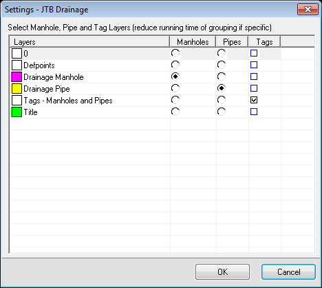
On the main window, click "1. Layer Settings" button
Specified layers for manholes and pipes. You can assign more than 1 layer, but a layer defined as manhole layer cannot be a pipe layer, and vice versa.
Specified layers for tags. Tags also can be put on more than 1 layer.
Note: JTB Drainage will automatically detect tags and arrows associated with manhole or pipe. This process take quite a long running time. Therefore you should be specific when using layers in your drawing to reduce the number of objects to be analysed, hence, reduce running time.
Associate Tags with Manhole or Pipe object
Tags (texts and mtexts and flowing arrows) will be automatically associated with manhole or pipe in case of:
- They have leader points to manhole or pipe
- They are placed near enough to manhole or pipe
- Arrow is aligned to pipe
Associated tags correctly help you edit your drainage plan easily.
When editing, if Manhole ref. (name) change, tag's text will reflect. So does the pipe's diameter tag. If cover level or invert level change, text content of "CL: ..." or "IL: ..." will be updated automatically. Levels change cause flowing direction on pipes change. This will be reflected immediately on associated flowing arrow tags.
In a high-density plan where objects are very close to each other, associated tags might not be correctly detected. Then, you have to check and edit them manually by click "2. Associate tags with manhole and pipe" command button:
- You will be asked to select manhole or pipe. (Note: manhole or pipe object should be on layer specified by Layer Settings)
- Once selected, the manhole or pipe and its associated tags will be highlighted.
- Type "R" to reselect associated tags.
- Type "A" to add (insert) new tag.
- Click on other manhole or pipe to make other check on its associated tags.
Note on Tag
- Data of Manhole and Pipe's properties stored in object itself. Tags are only reflections. To change property, click "Edit ..." button rather than edit tag.
- When Manhole's tag is MText, if the first text line is a single word, it is assumed to be manhole's ref.
- If text content like "CL = ...", or "CL: ..." found, a following numeric text is assumed to be cover level.
- If text content like "IL = ...", or "IL: ..." found, a following numeric text is assumed to be invert level.
- If pipe's tag text like 100%%c, it is assumed to be pipe's diameter.
Edit Pipe: textboxes move if pipe slope change

- Click on pipe and a Edit Pipe window will bring up
- Pipe's properties are: diameter; start level and end level; lock properties at start and end
- If found, manhole at each end of pipe also be displayed for you to quickly edit, or jump to its Edit Manhole window
- When pipe's levels change, you can see the textboxes moved reflecting the slope
After editing, click OK, you will see all associated tags updated. Drainage flowing arrows also change their directions as well if levels change.
Insert flowing arrow
Edit Manhole and connecting Pipes
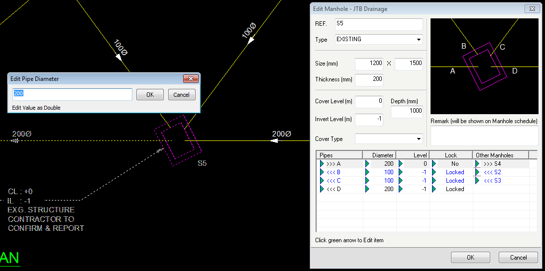
- Click on manhole and a Edit Manhole window will bring up
- Manhole properties are: Ref. name, type, cover type, size, thickness, levels, depth, and remark. These properties will be shown in manhole schedule.
- A list of pipes connect to manhole also display. You can see pipe's flowing direction indicated by arrow <<< or >>>
- On this list, you can quickly edit these pipes directly by clicking to the green arrow button.
- If pipe's level is locked to manhole's invert level, changes will be synchronized between these objects (including other locked pipes as well)
- You can click on the green arrow to jump to Edit Pipe window, or jump to other Edit Manhole window.
After editing, click OK, you will see all associated tags updated. Drainage flowing arrows also change their directions as well if levels change.
Please contact us with your interest in JTB Drainage or if you want support for other CAD products like BricsCAD.